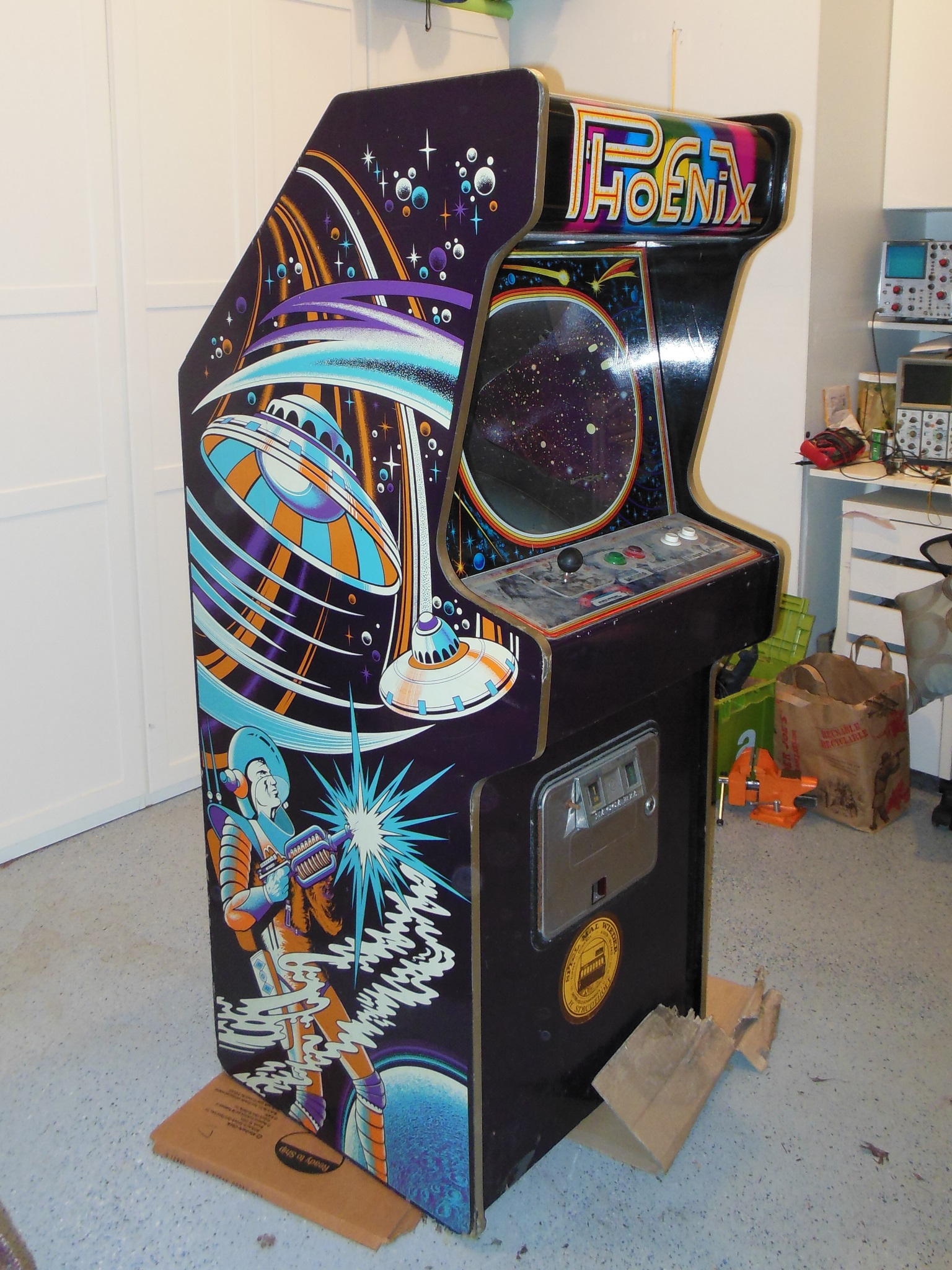
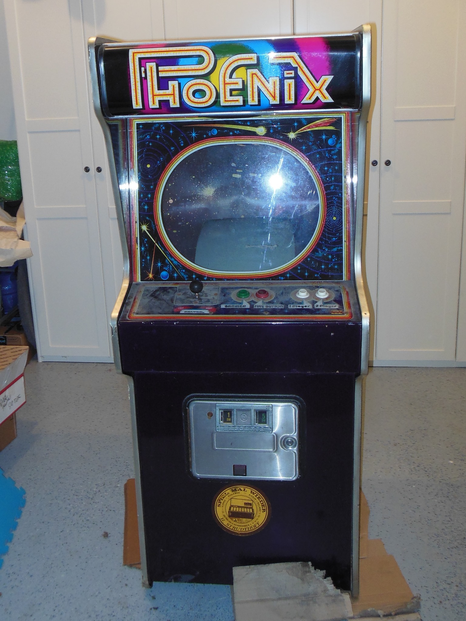
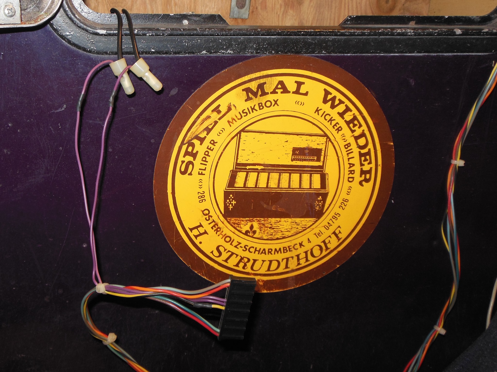
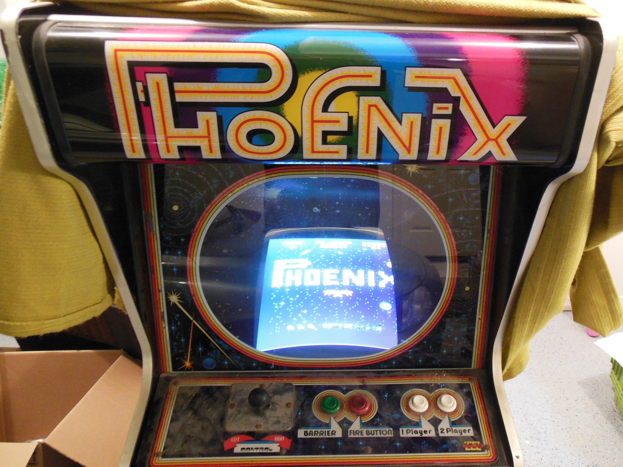
I can't remember where this game came from, but since it has Deutschmark coin entry plates and a German operator label on the front it seems likely it was originally operated in Germany.
|
|
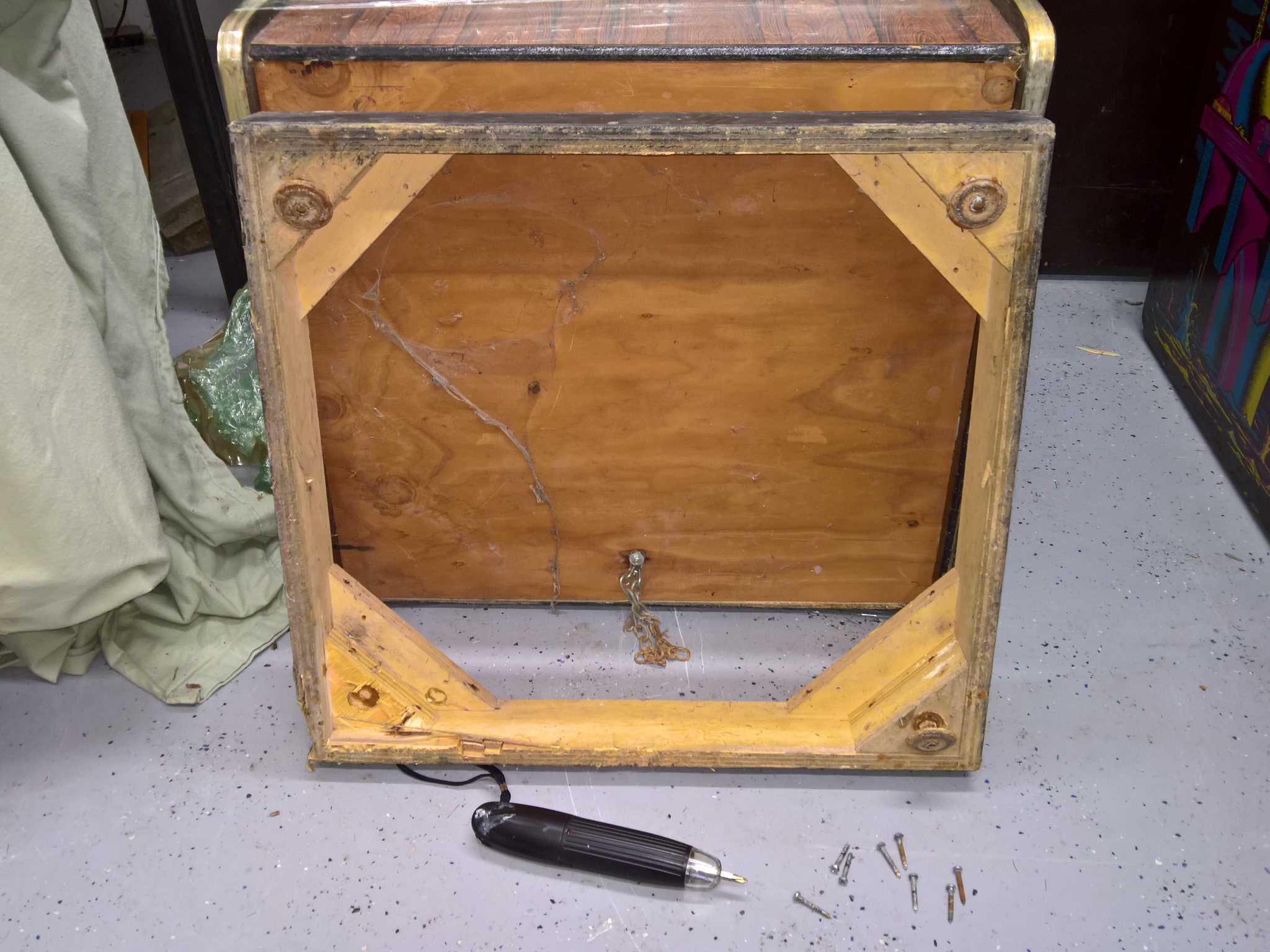
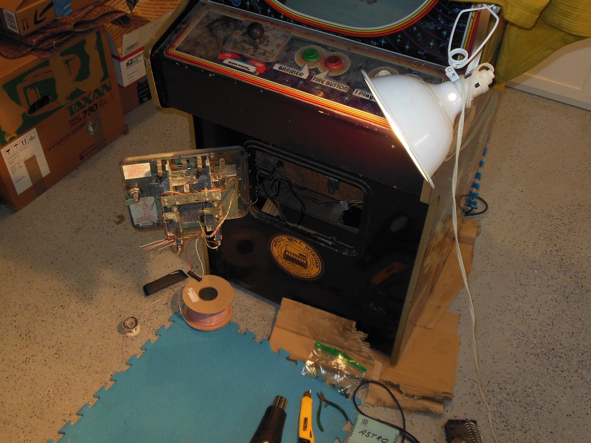
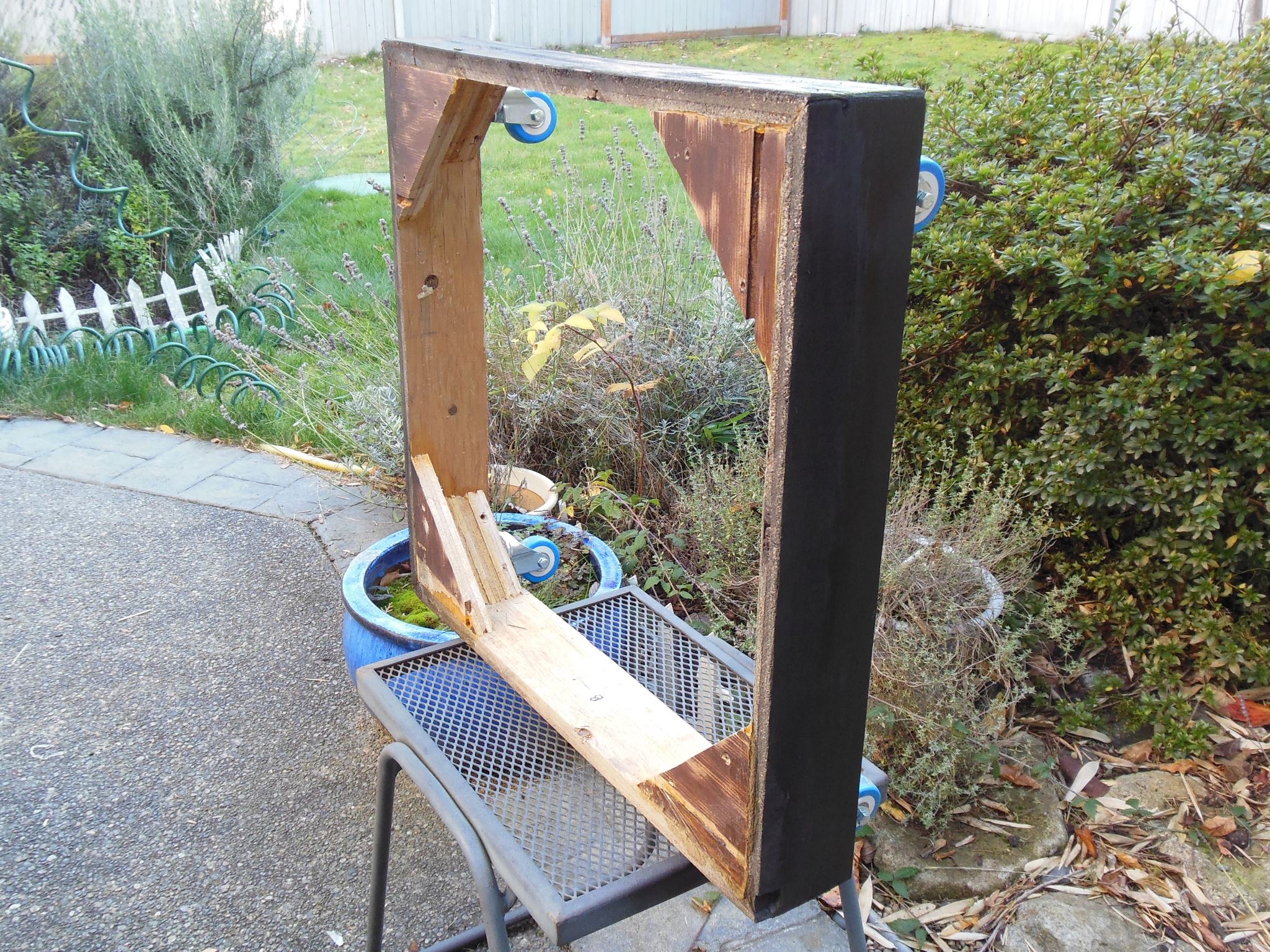
Before looking closely at this game I'd already noticed that it was missing it's base and thus I'd need to reproduce one for it. I selected another cabinet to remove the base from to use as a guide to make a reproduction base in future.
The bases on these games are simply attached by eight screws. This particular base also needed some repair work I planned on doing at the same time whilst it was off.
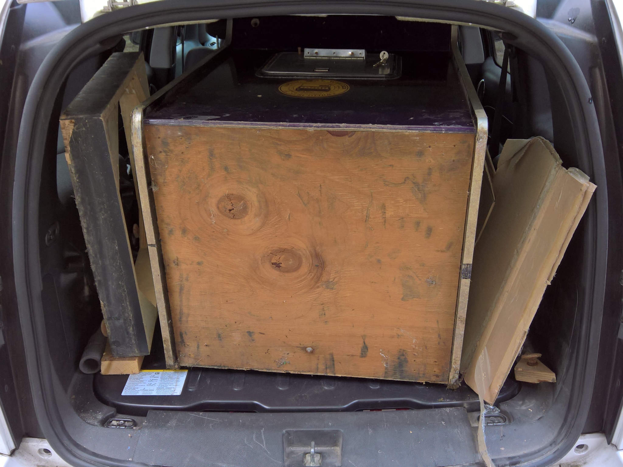
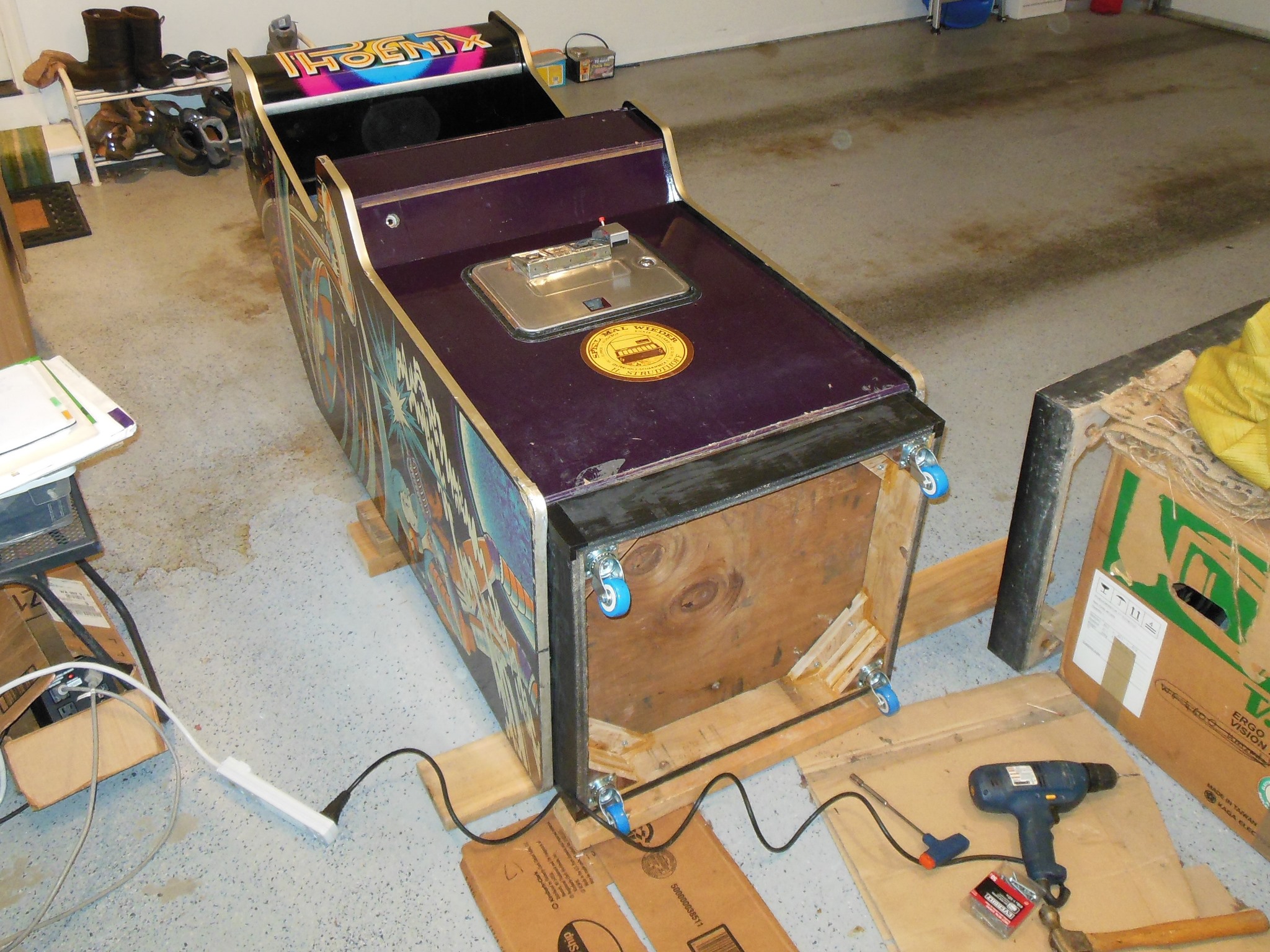
That said, with the Phoenix game loaded into the car there were no screw holes I could see to indicate that it originally had a base fitted - only four foot screws in each corner. The slightly later flat marque cabs I'd often seen without bases but not a full size curve marque cabinet. Since I'm a tall person and all my other curve marque cabs had bases I decided to still go ahead and reproduce a base for this one to match.
|
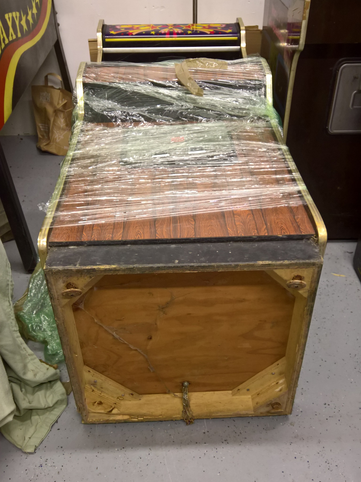
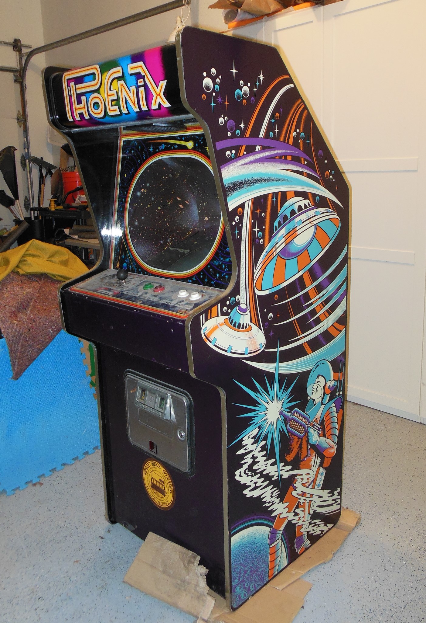
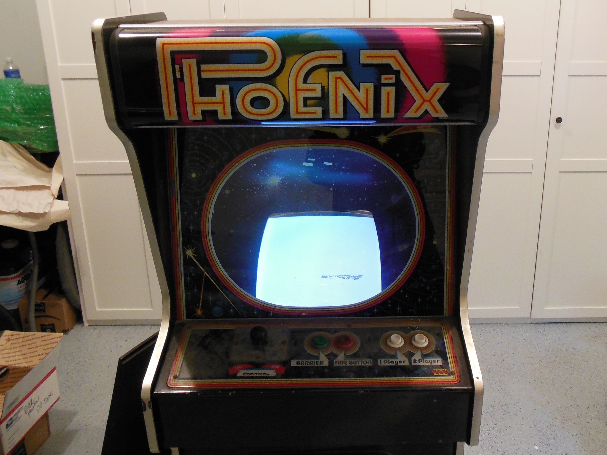
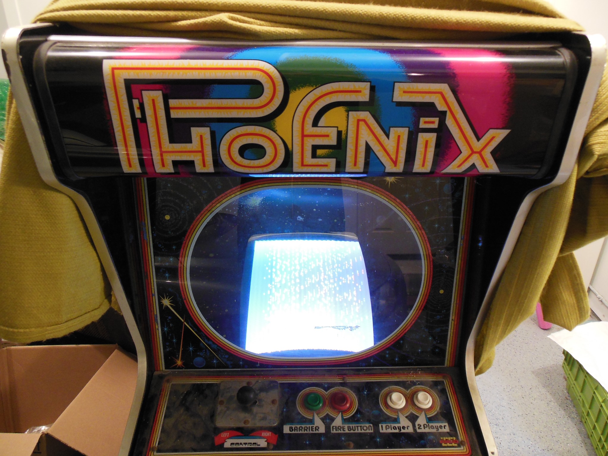
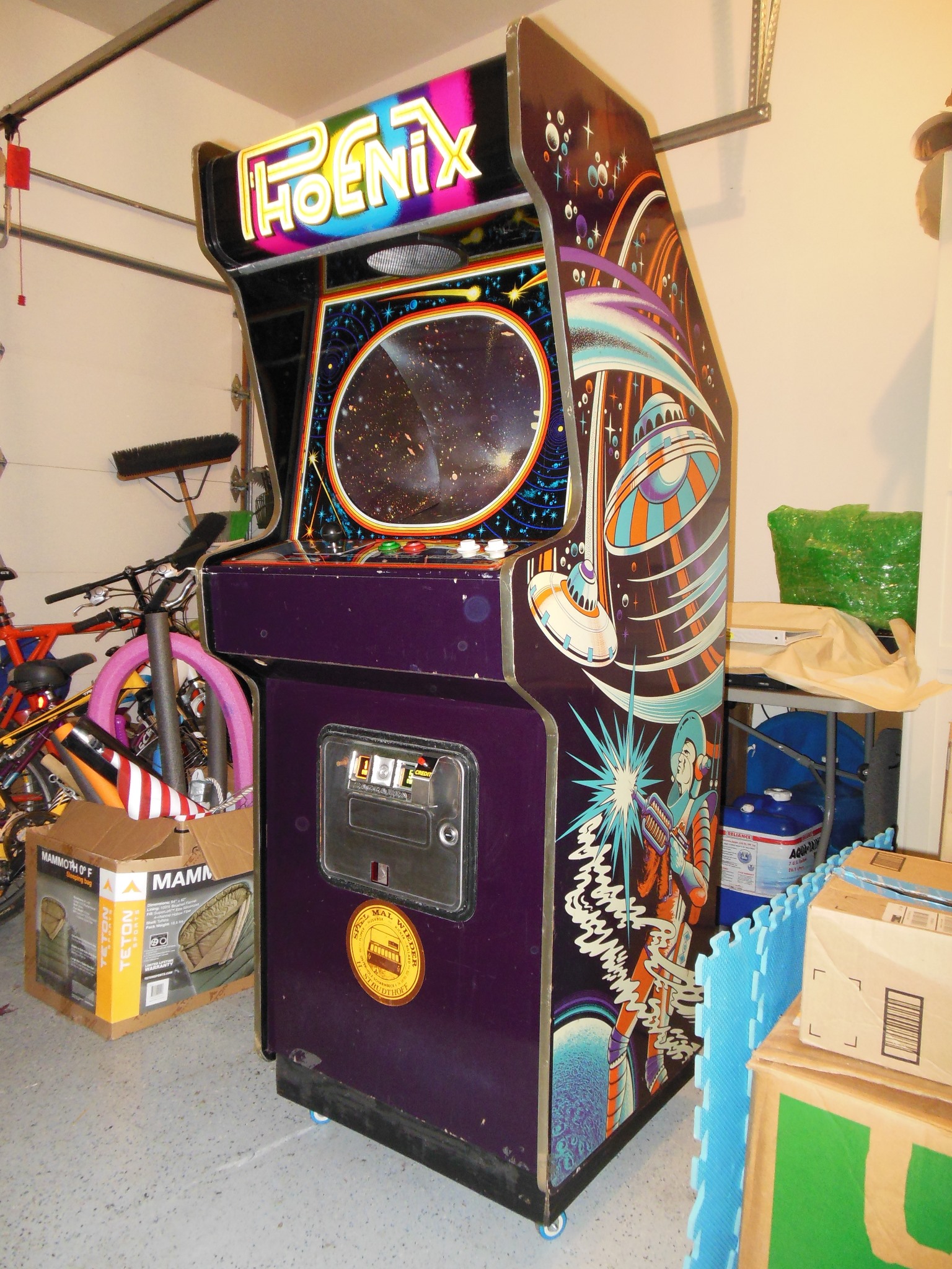
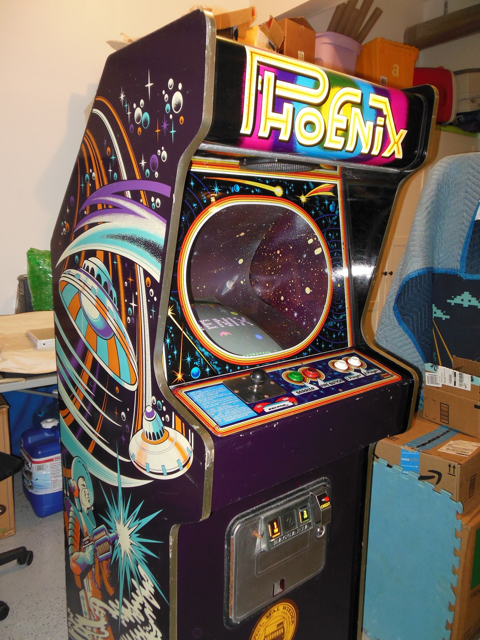
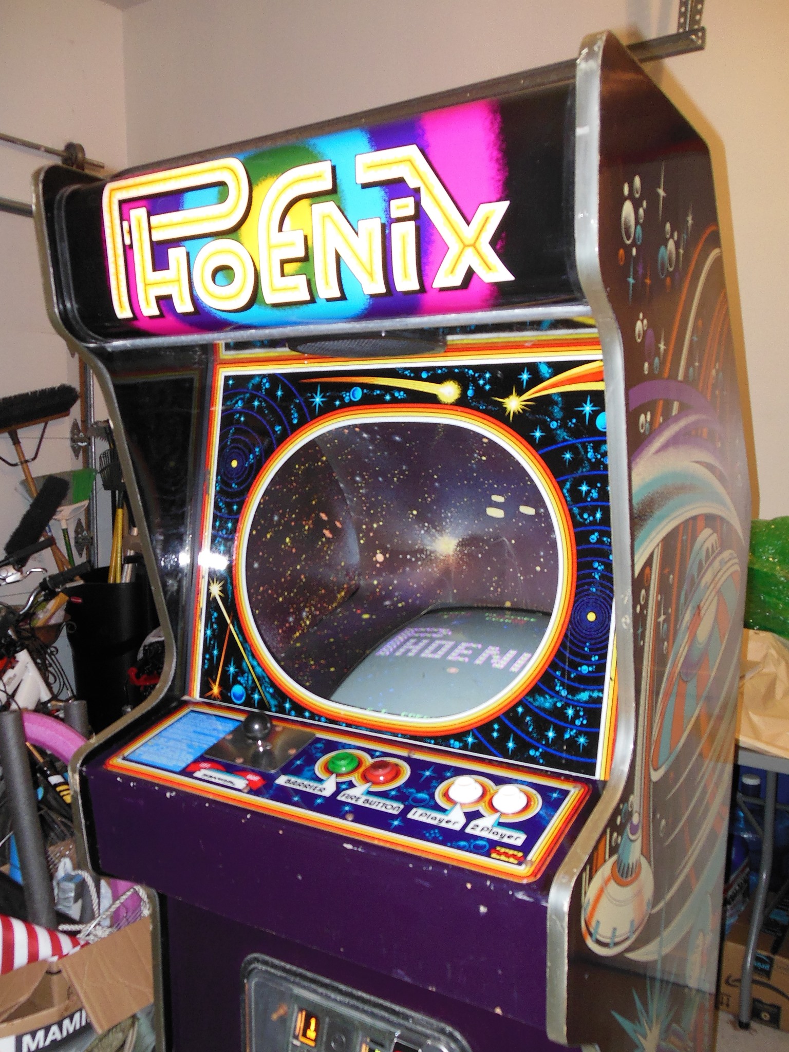
The side art and cabinet was in excellent condition with few scratches & dings. The base was missing but the cabinet was otherwise woodwork complete.
|
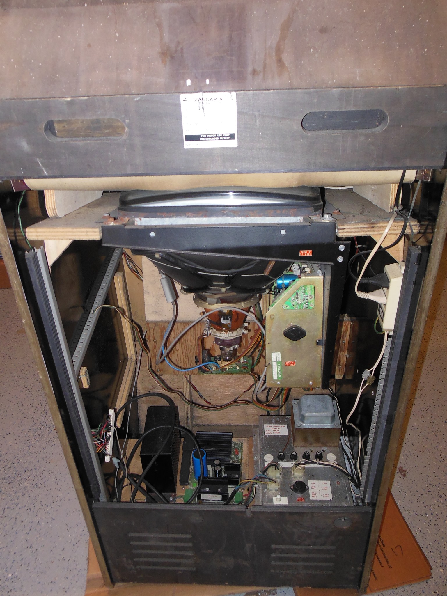
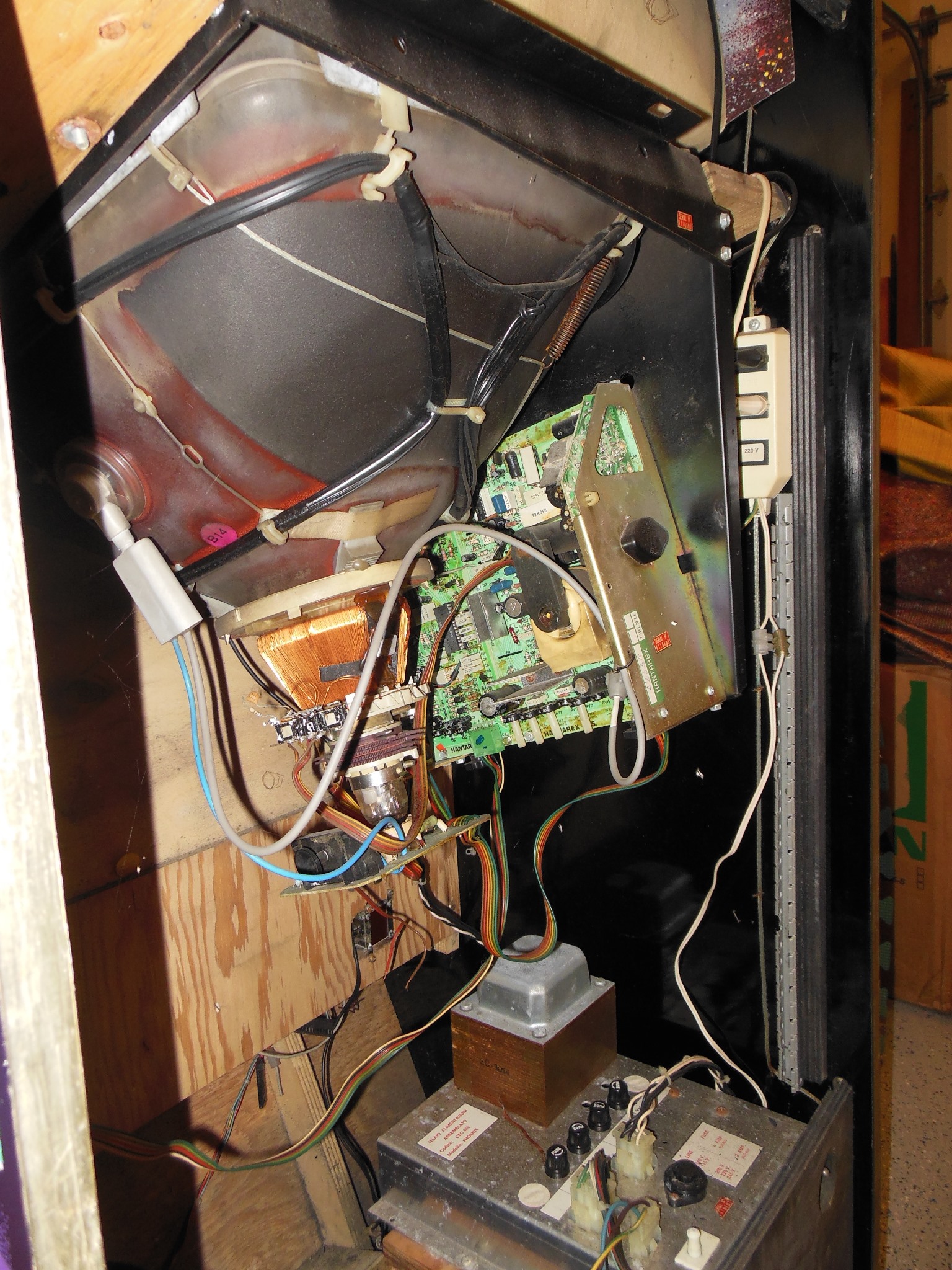
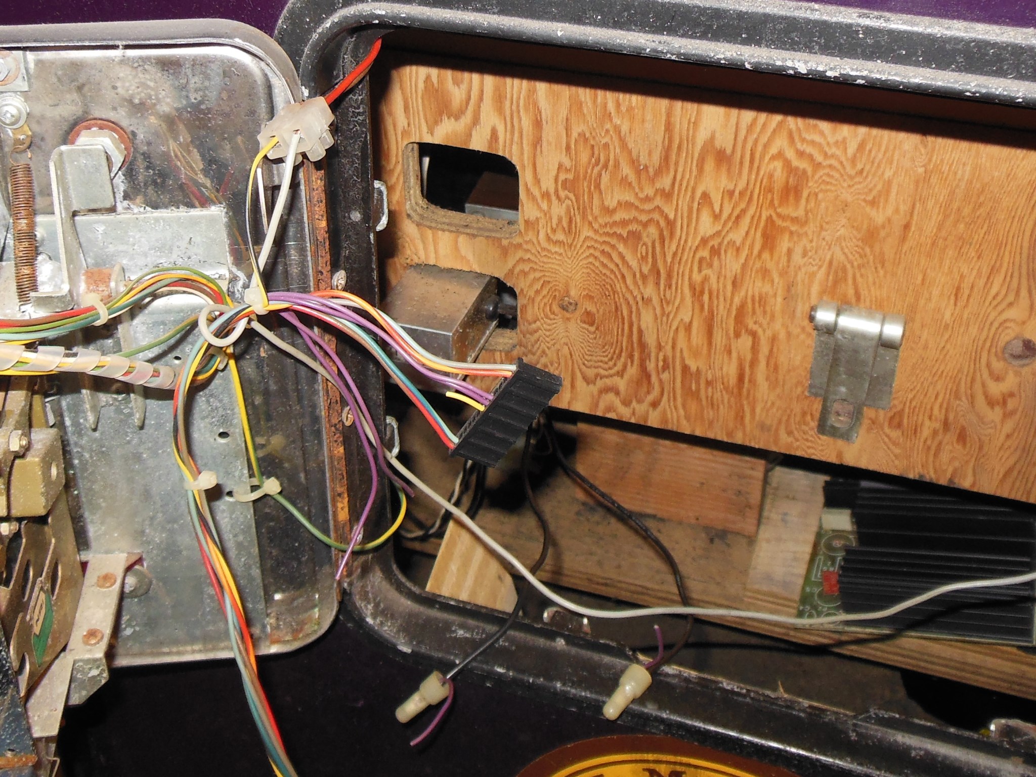
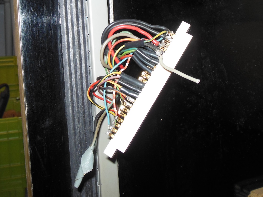
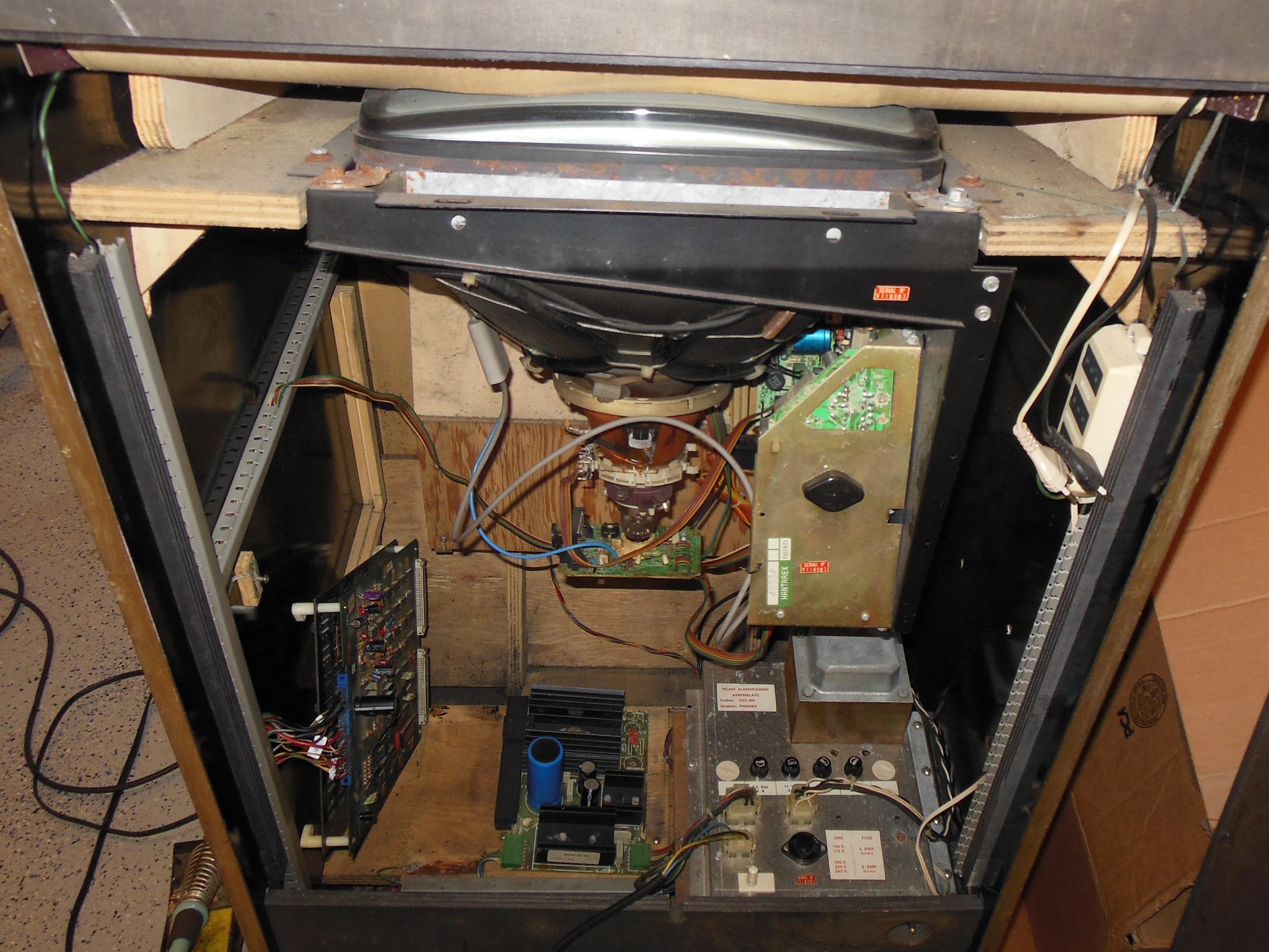
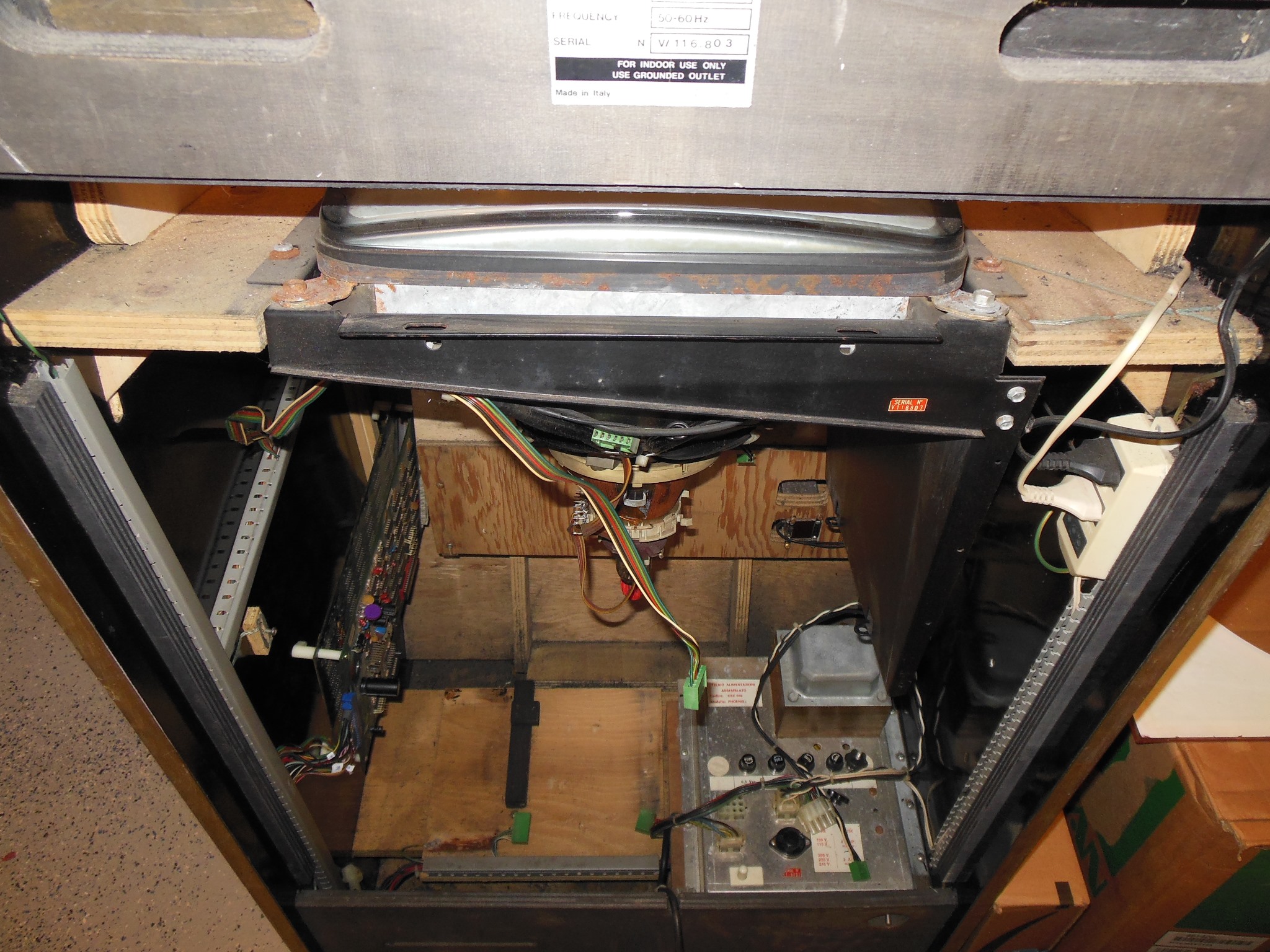
Internally most of the rear wiring looked intact except for a terminal block on the marque light socket input and the game PCB edge connector that had been changed and rewired to convert the game to something else. From the edge connector there was also a further wire hacked in running to the coin door.
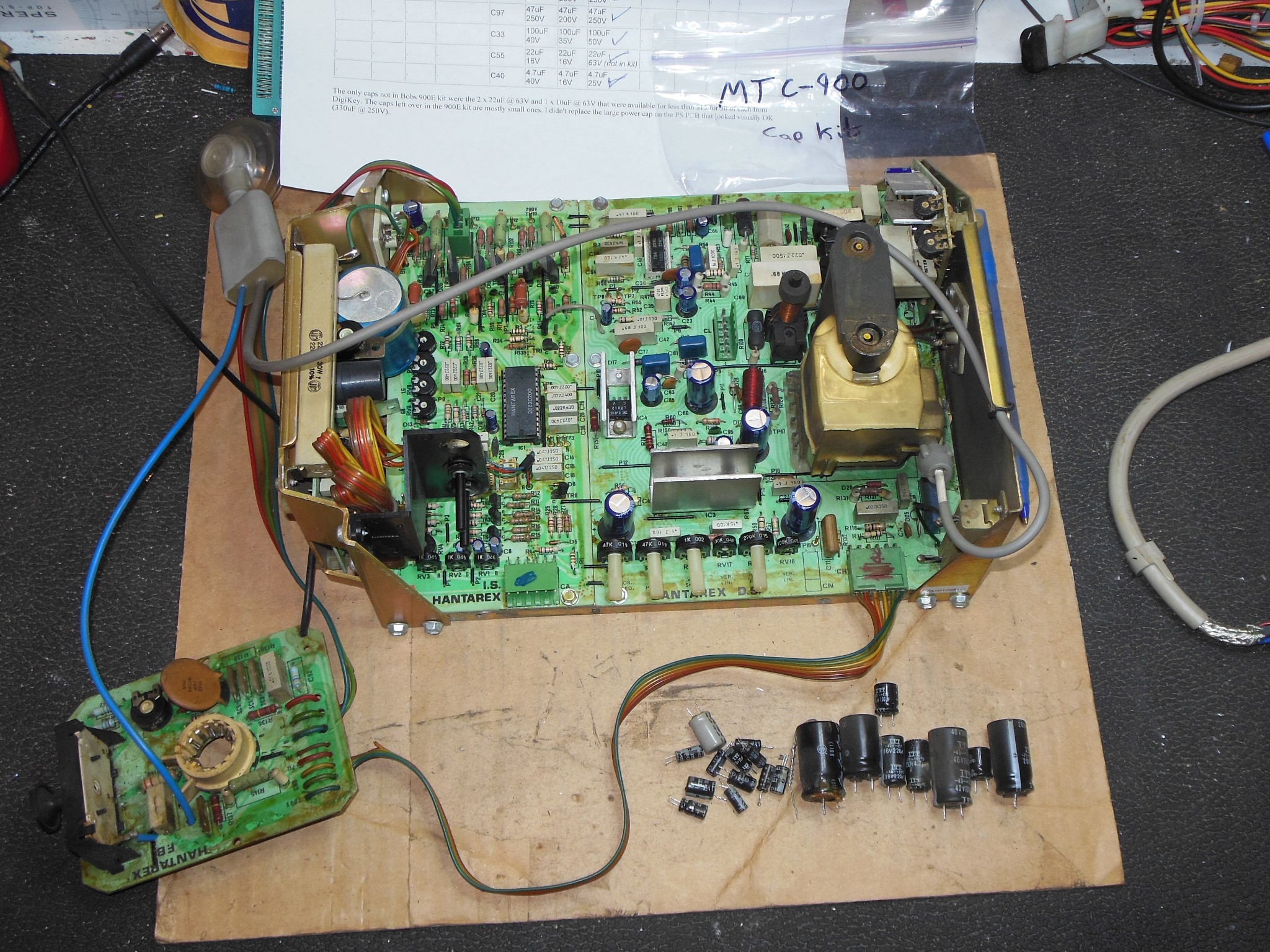
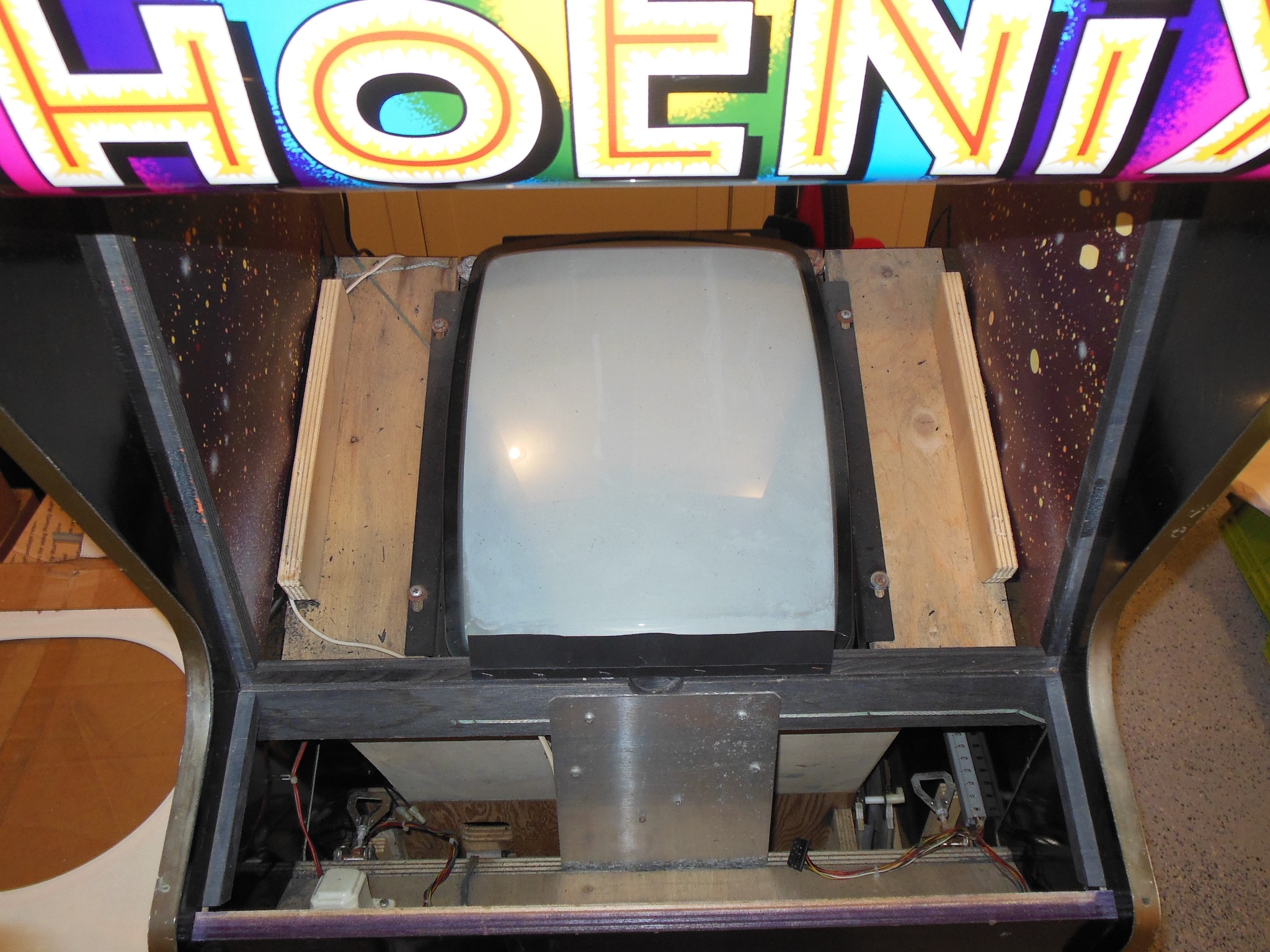
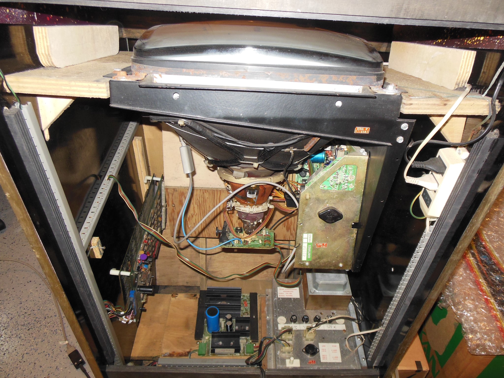
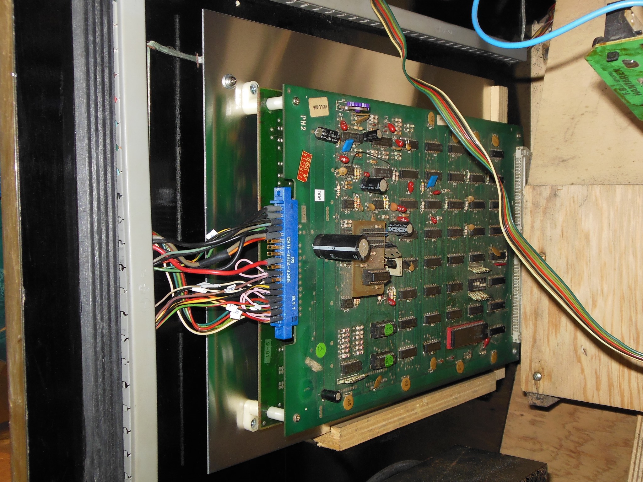
The monitor was a very early run of the Hantarex MTC-900. I'd originally selected this game to restore based on a push to get through all the Philips KT-3 monitor based games and thus hadn't expected a Hantarex inside this one.

|
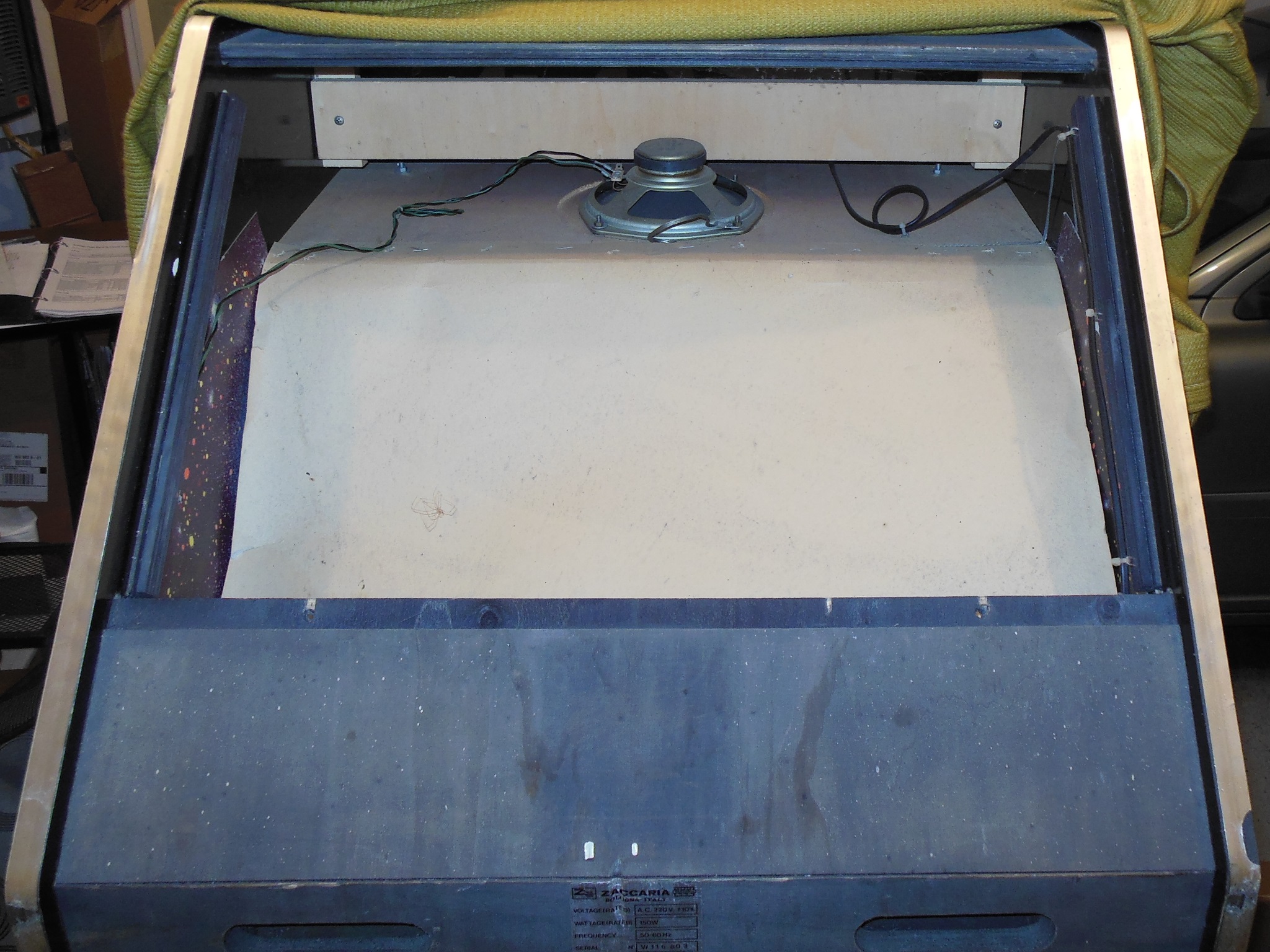
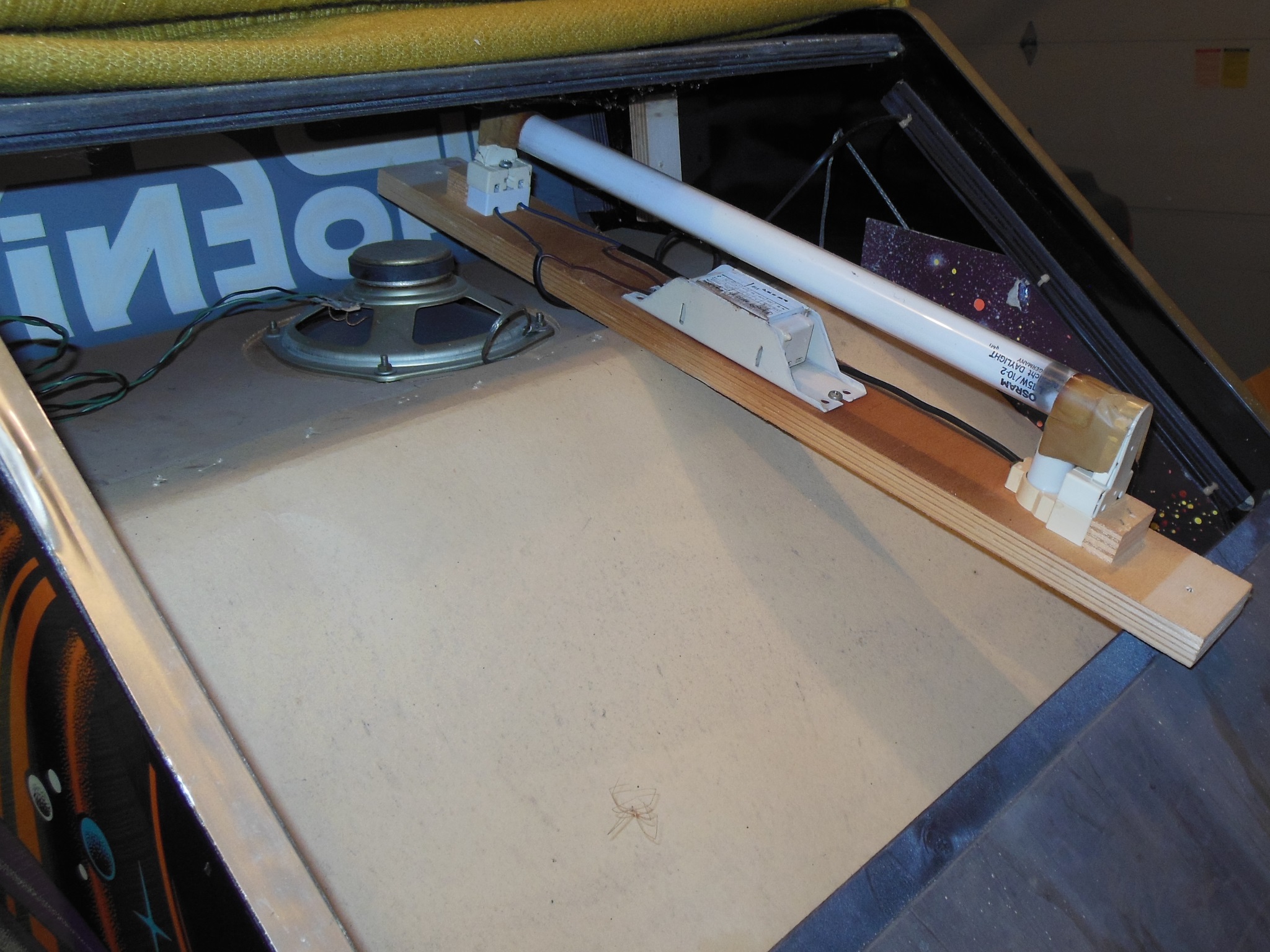
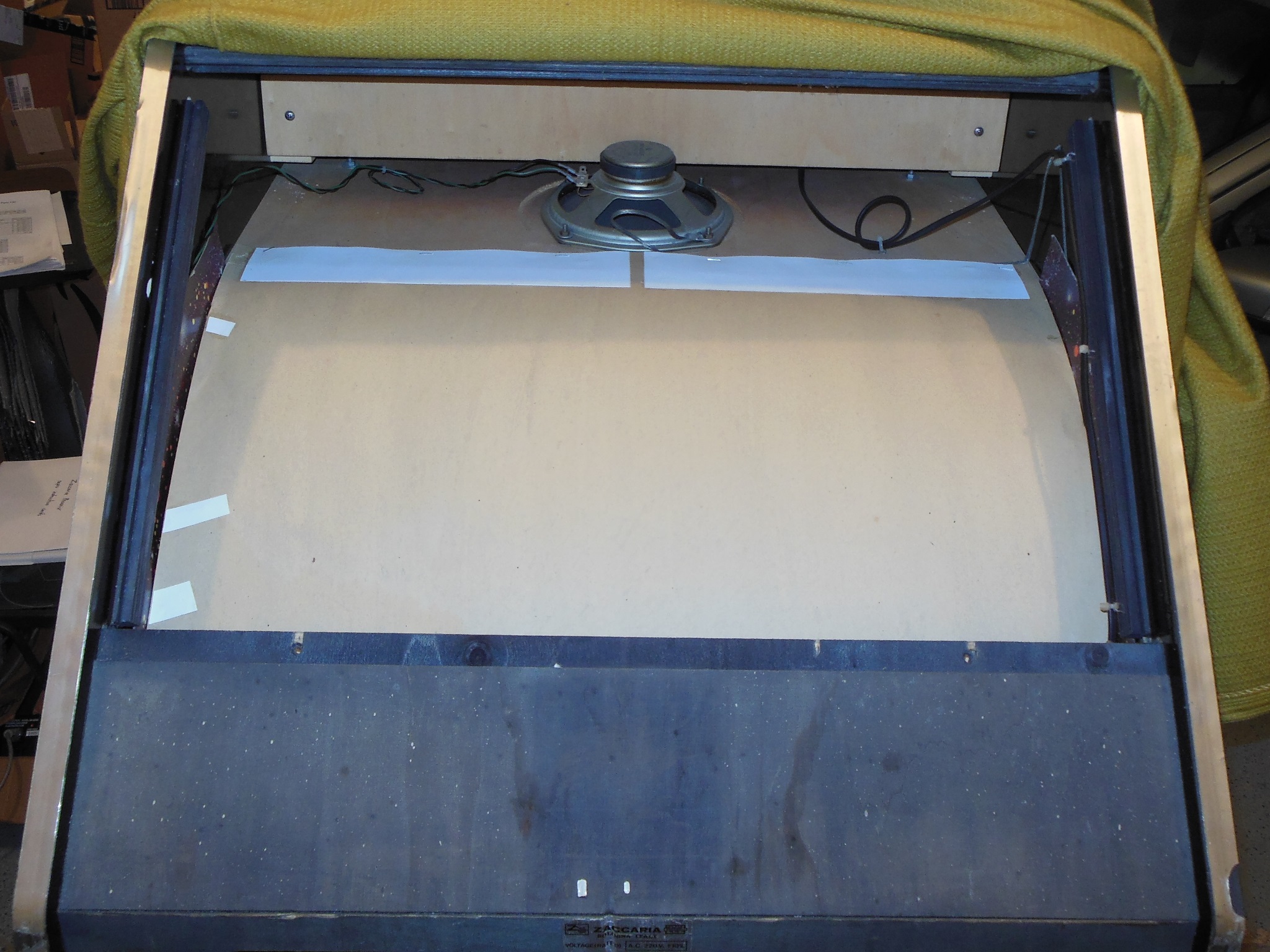
The top marque light rear access hatch was easily removed to reveal an intact marque light assembly & speaker.
|
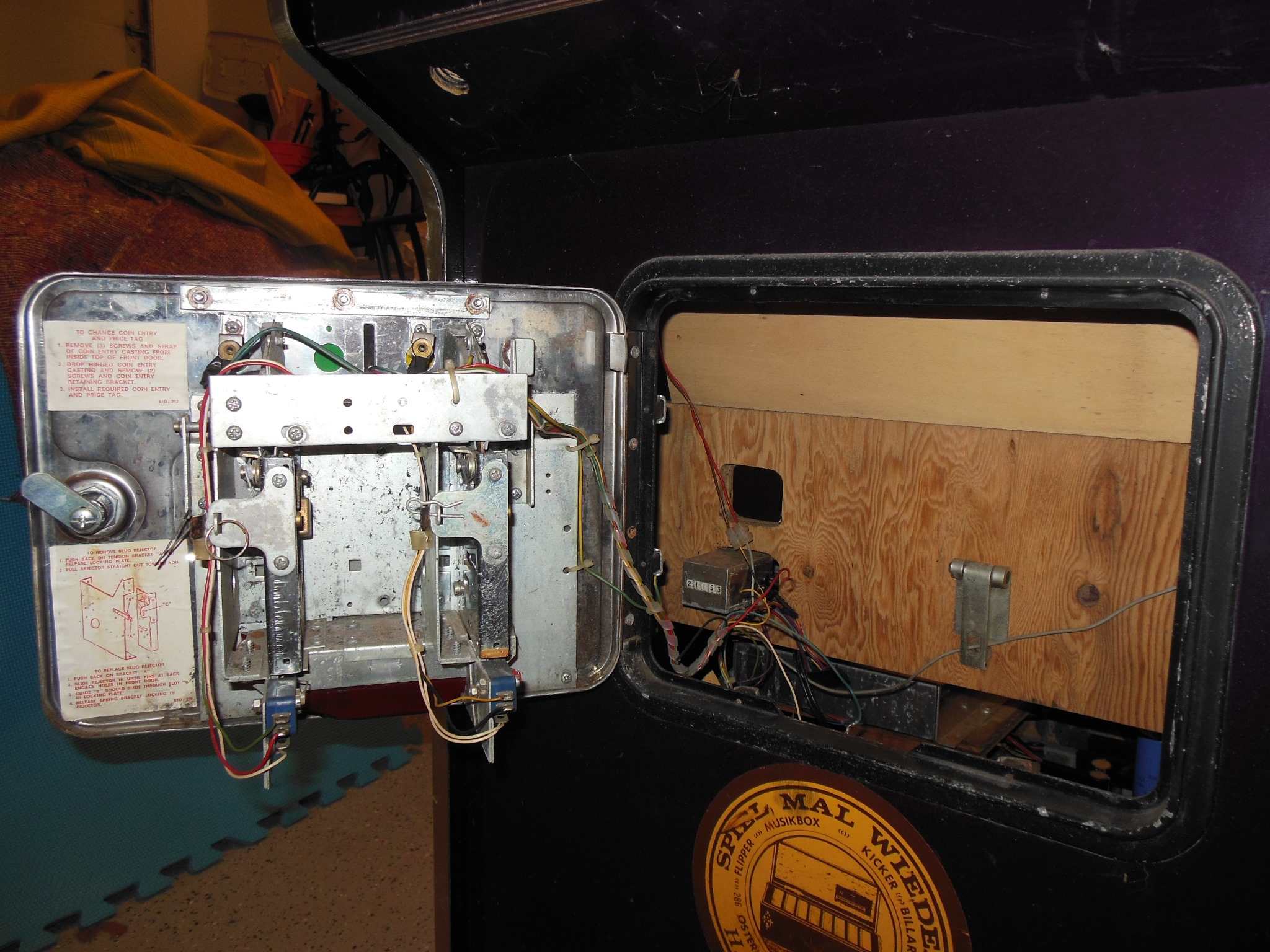
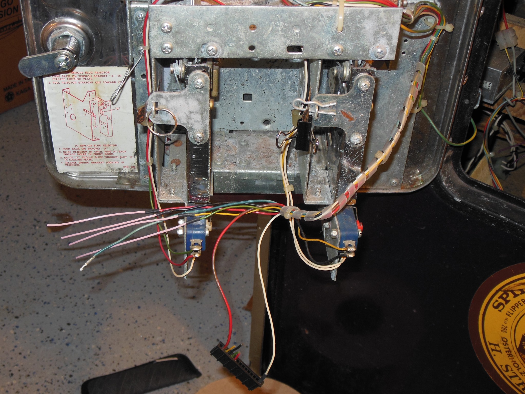
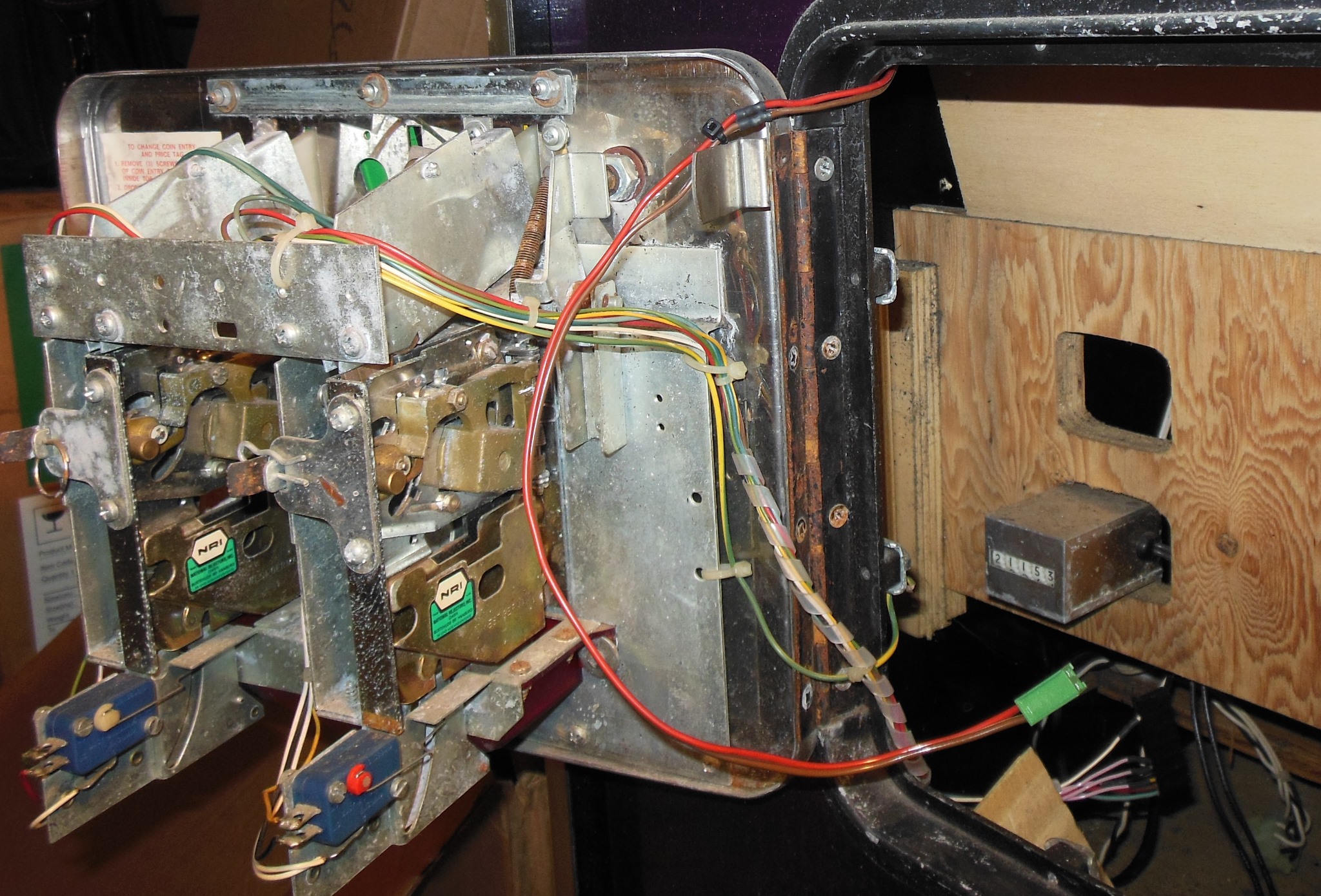
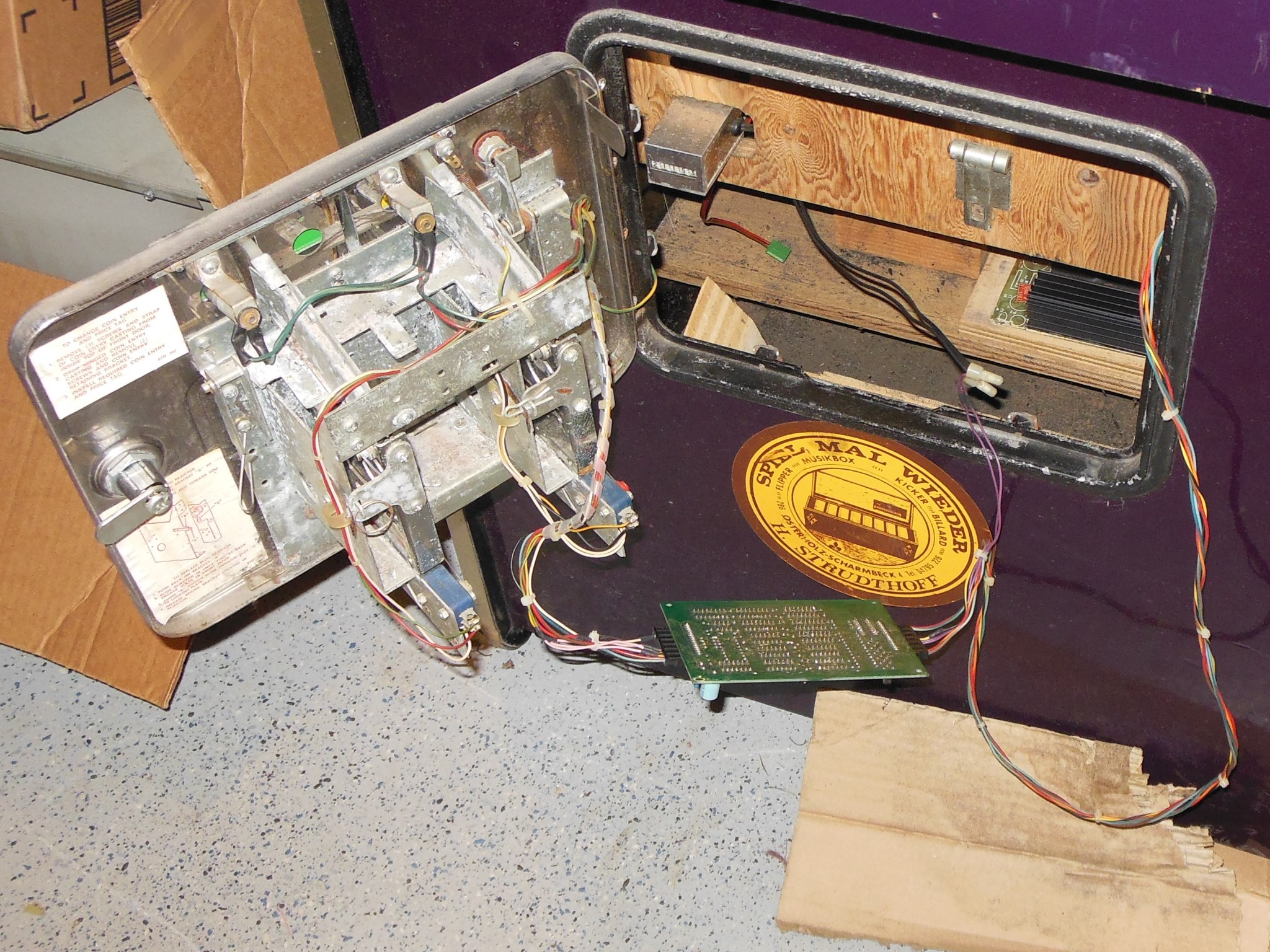
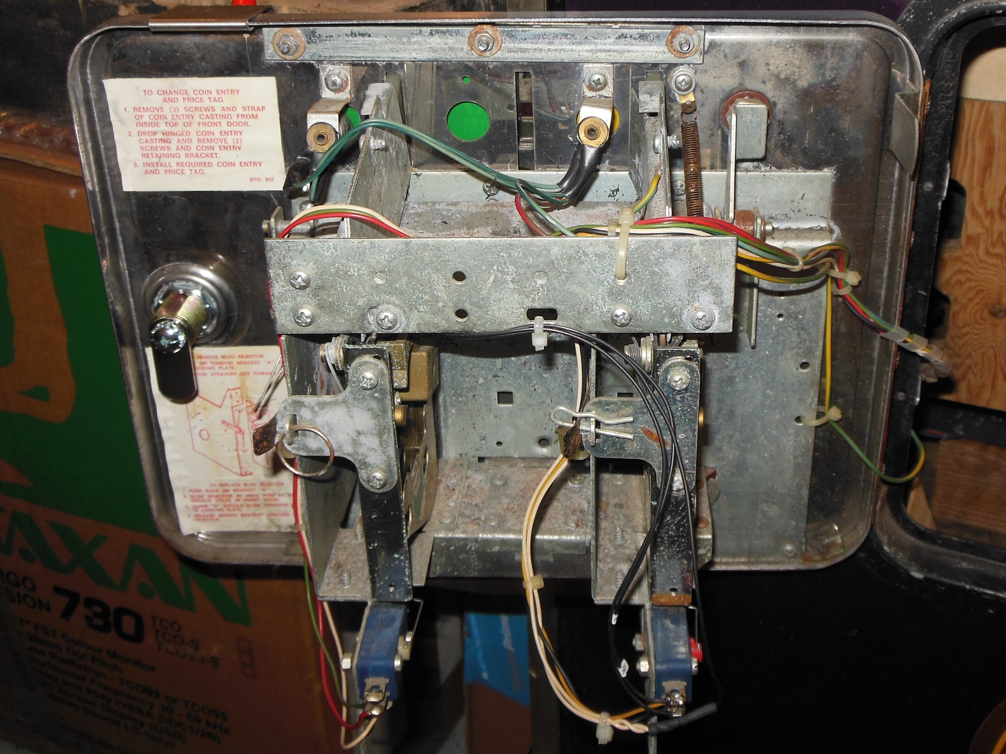
The coin & credit wiring was in much worse shape than the rear wiring - the credit PCB was missing, connectors cut and wiring hacked :(
|
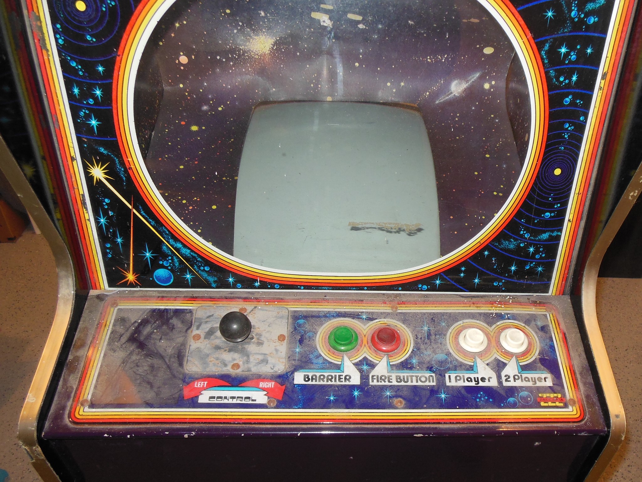
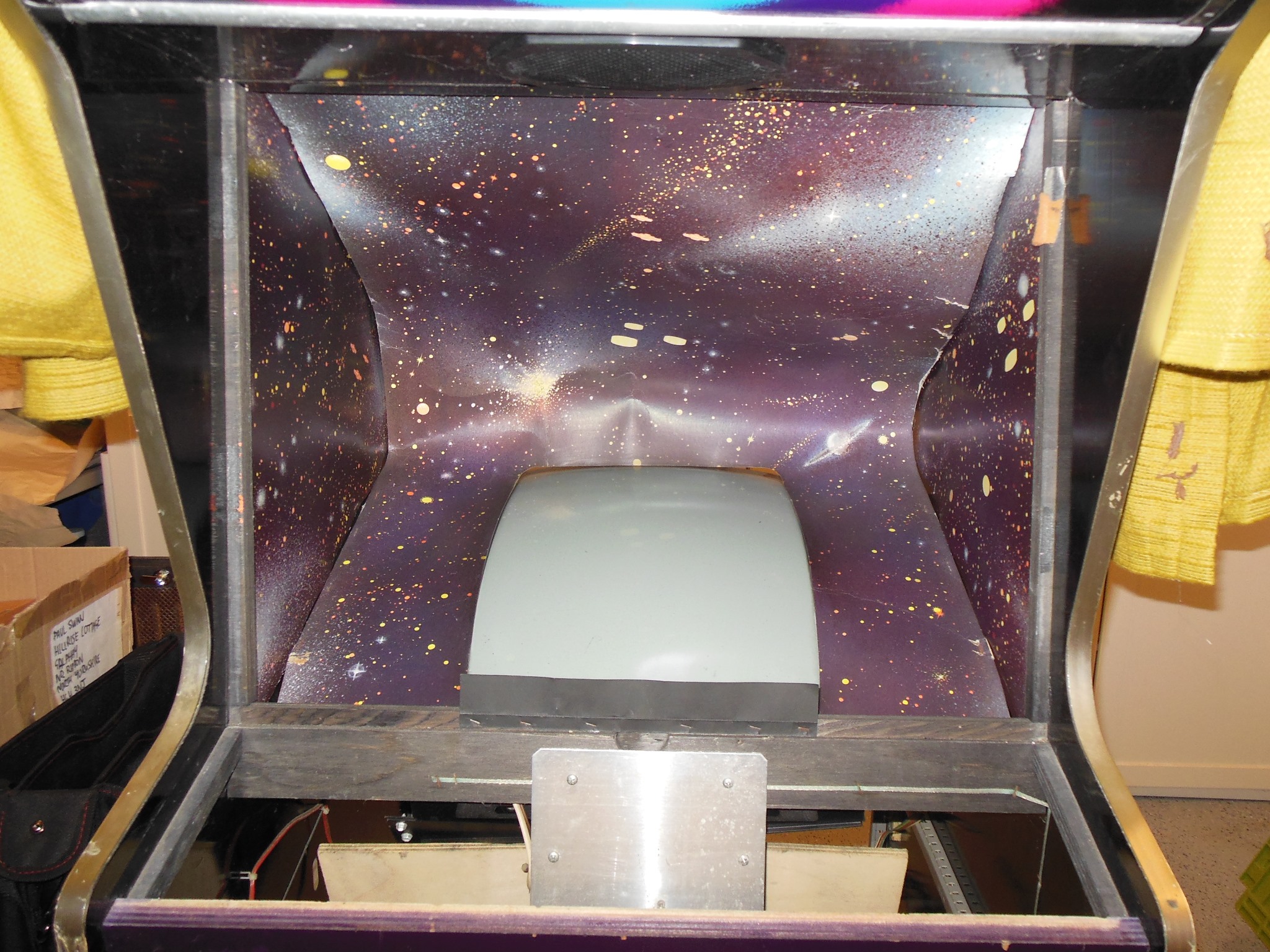
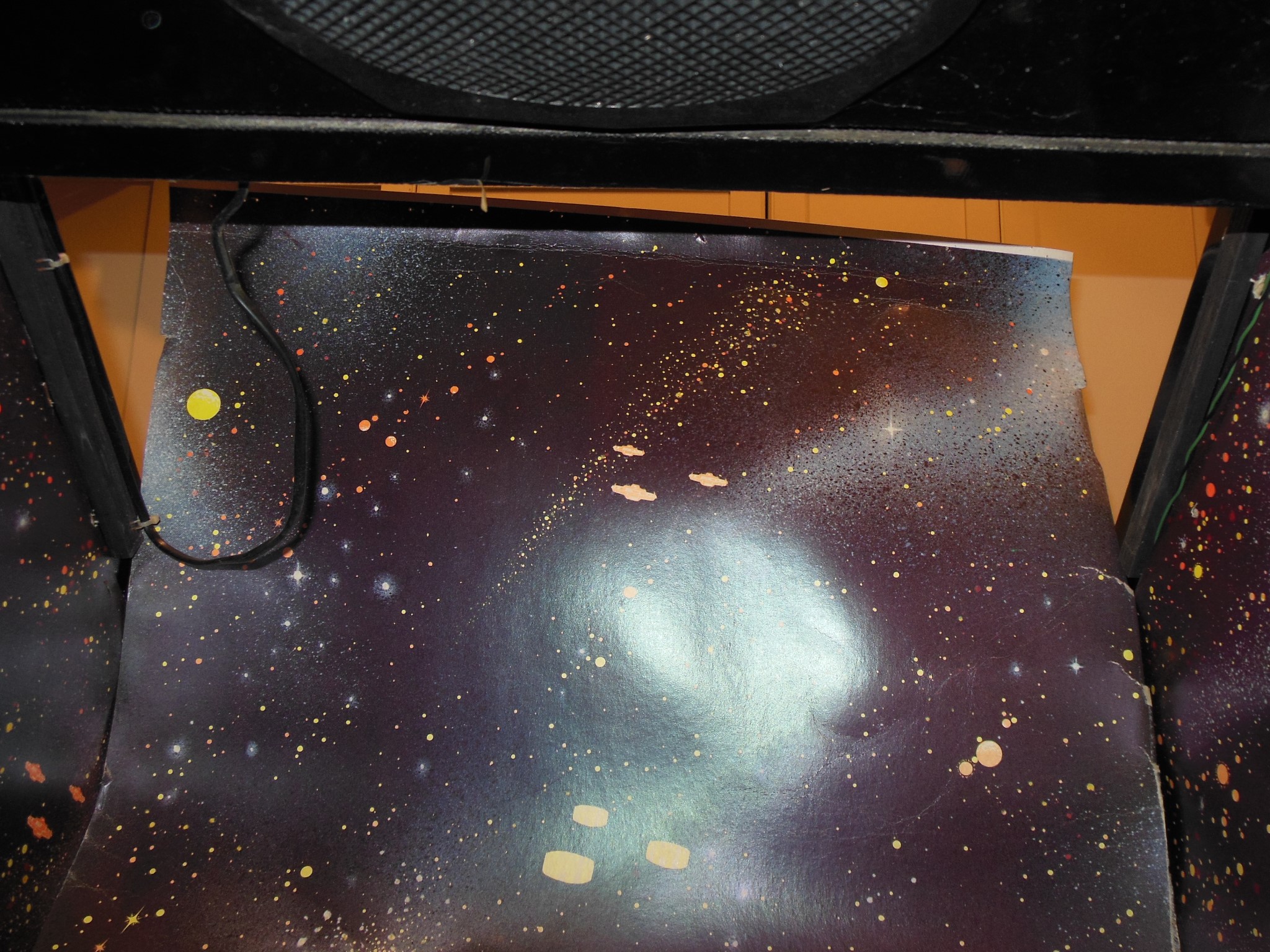
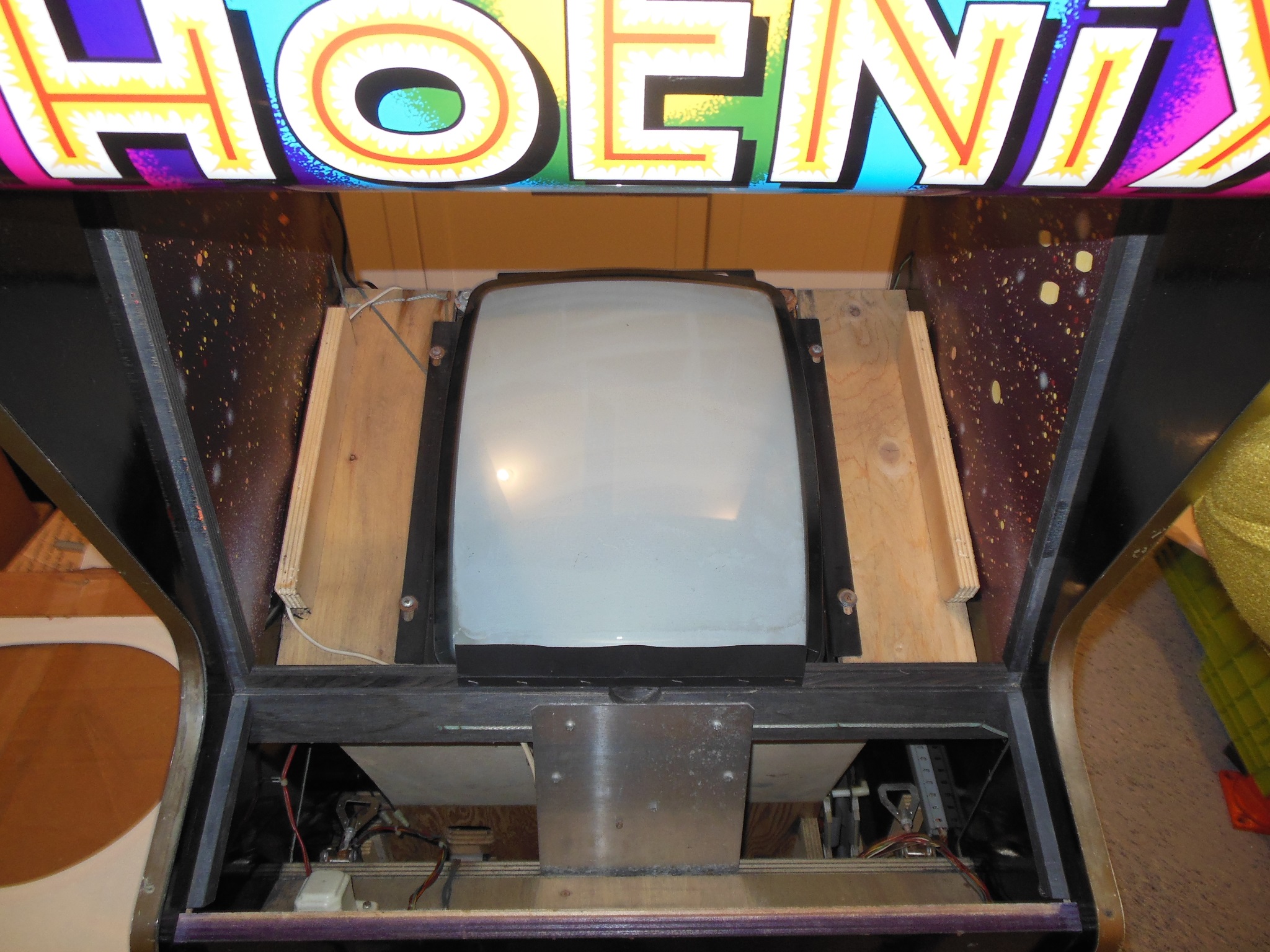
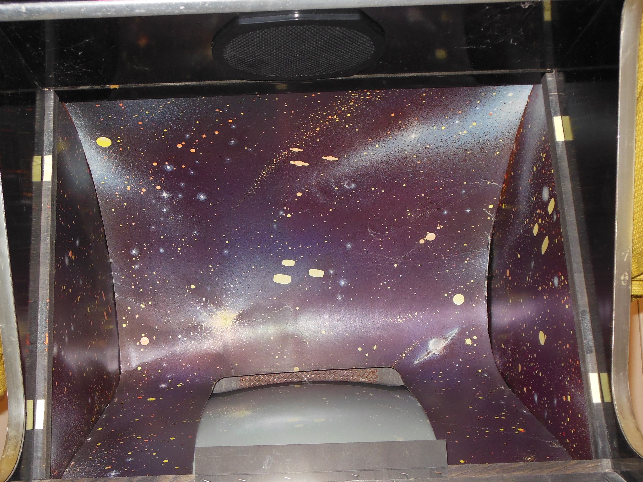
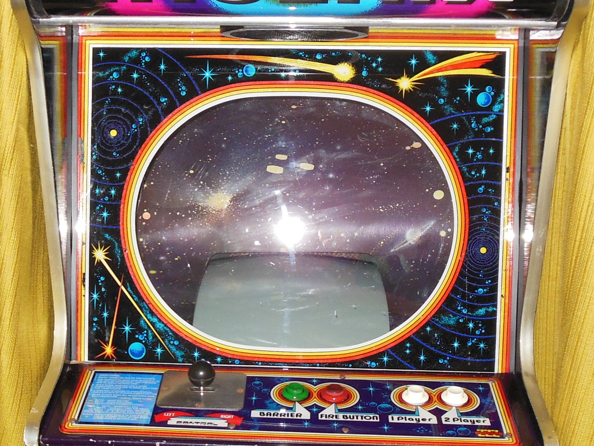
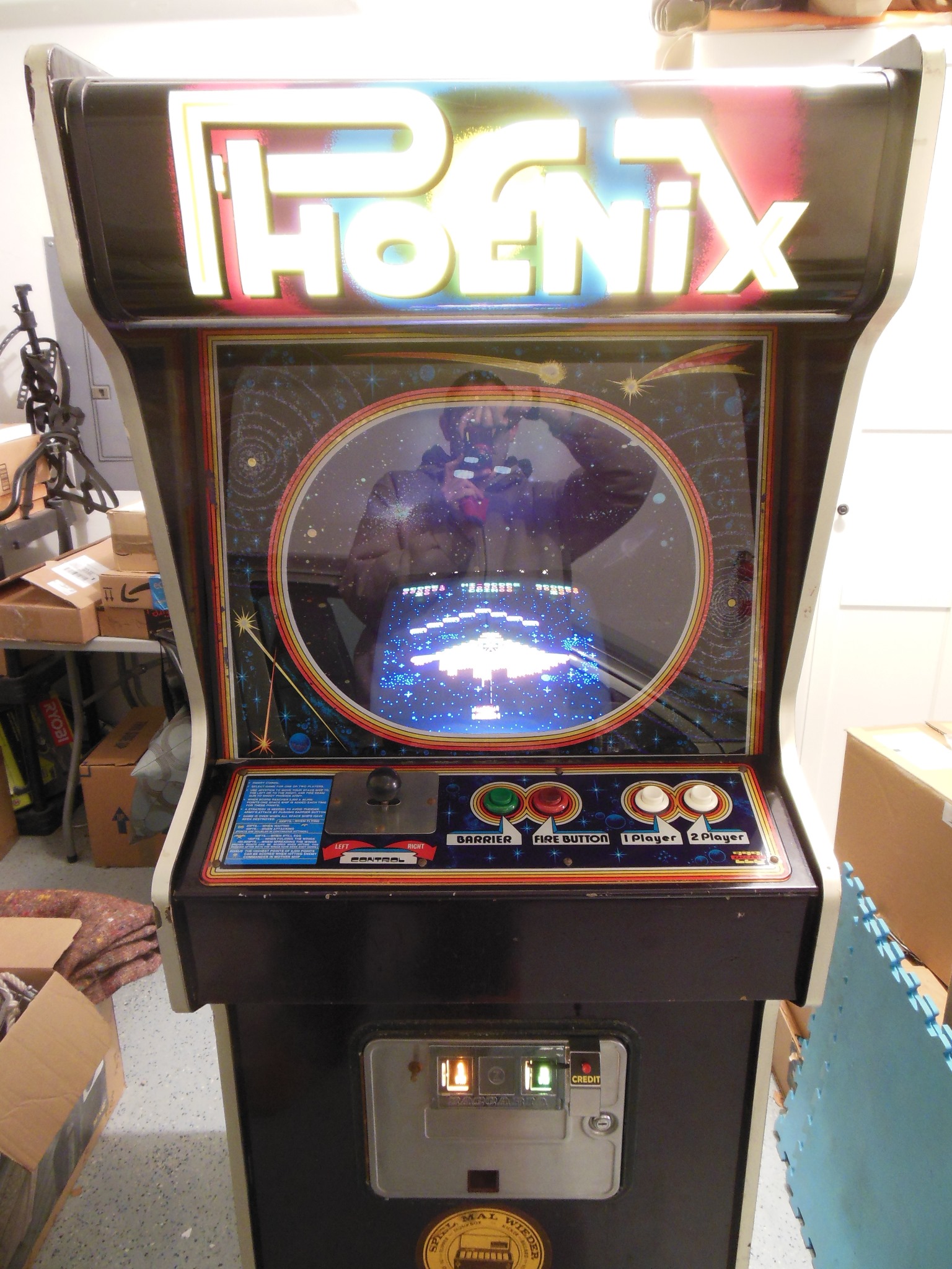
The control panel was complete aside from missing instruction sheet and unhacked. There were few cigarette burns but some heat deformity around the player start buttons. The monitor glass artwork was in poor condition with missing areas in places. The glass was also missing the side edge beading. Inside, the monitor surround cardboard looked complete if a little beat up.
|
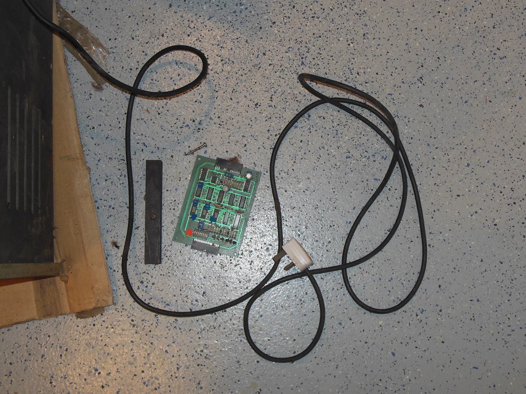
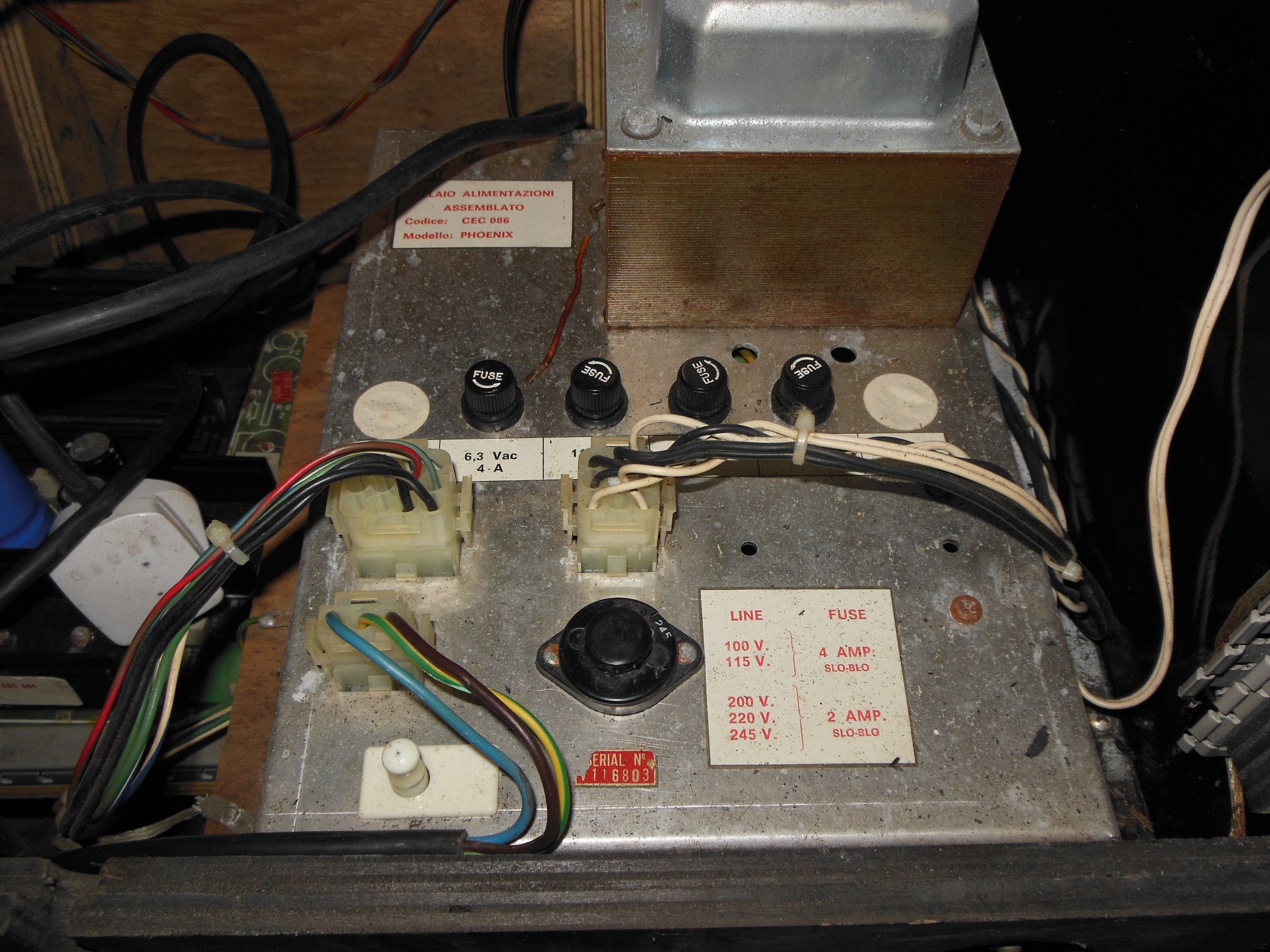
I found the credit PCB and power PCB mounting guide in the bottom of the cabinet.
|
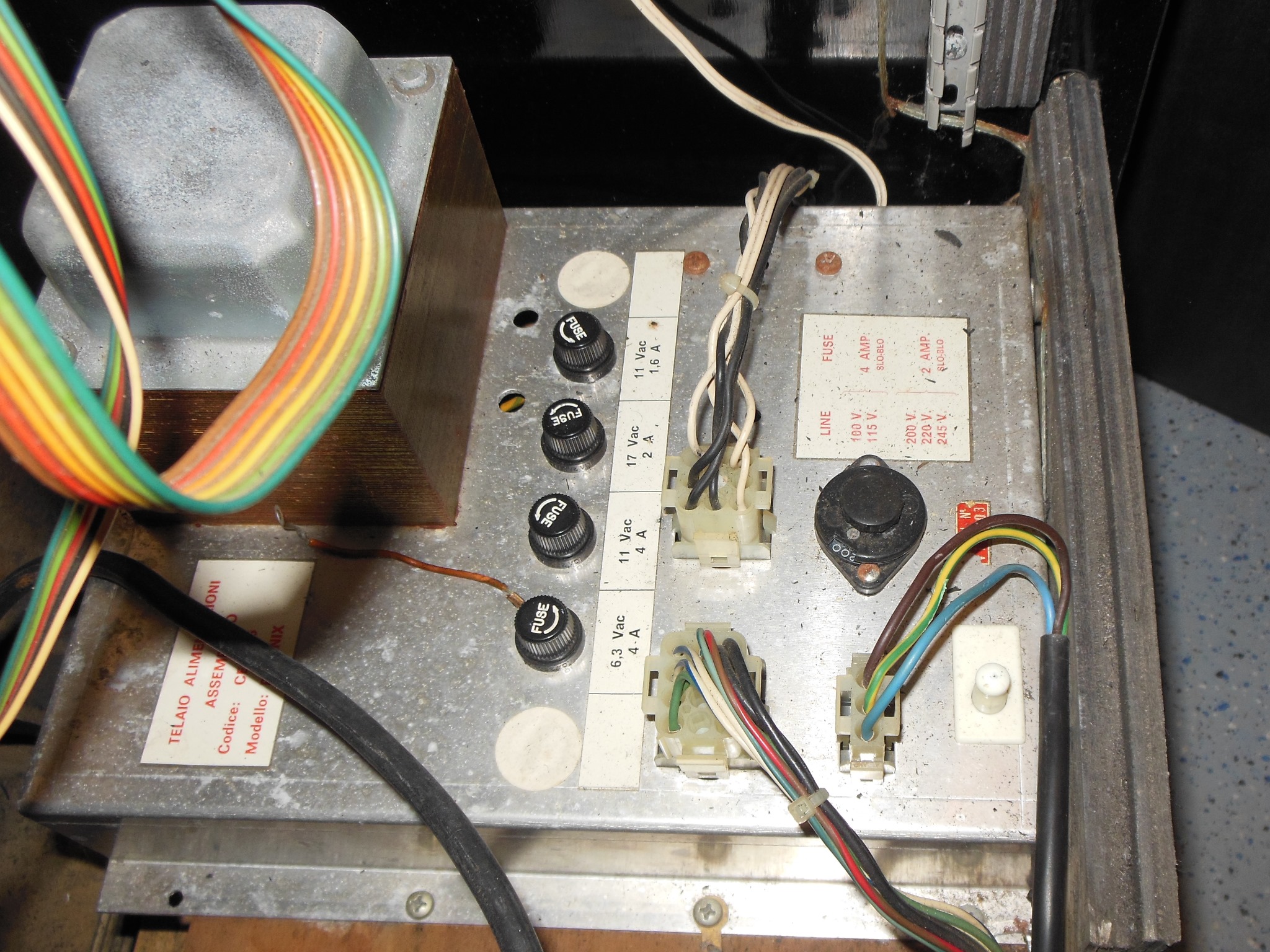
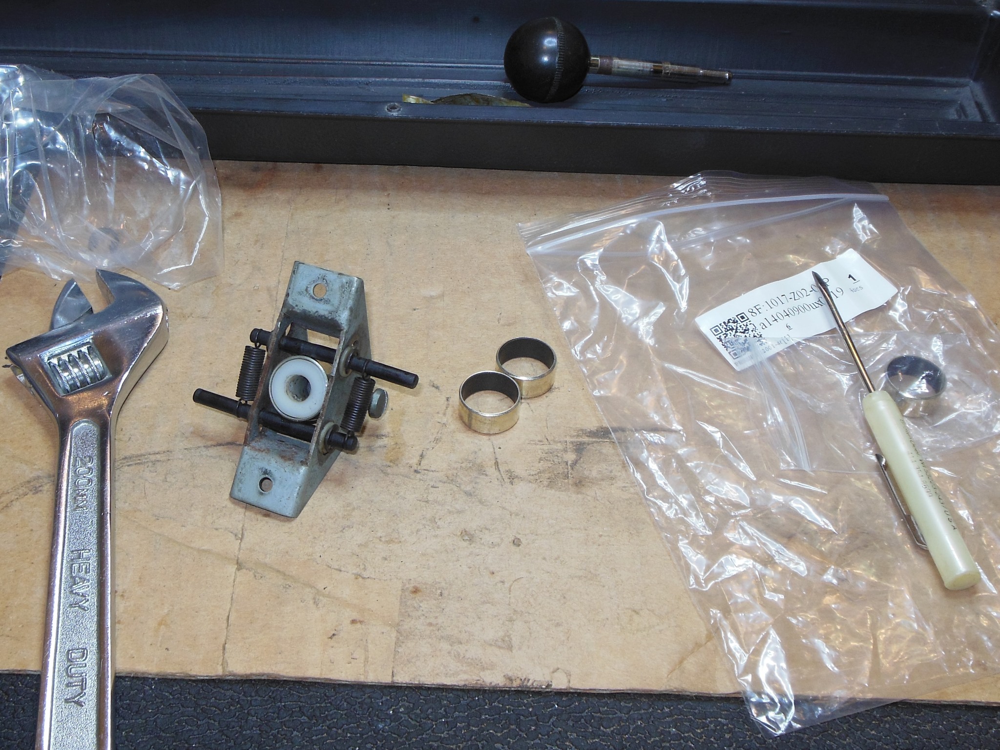
As found the voltage selector plug was set to 200V thus I changed it to be 245V to match the 240V supply I'd been using here in the US.
 ,
,
|
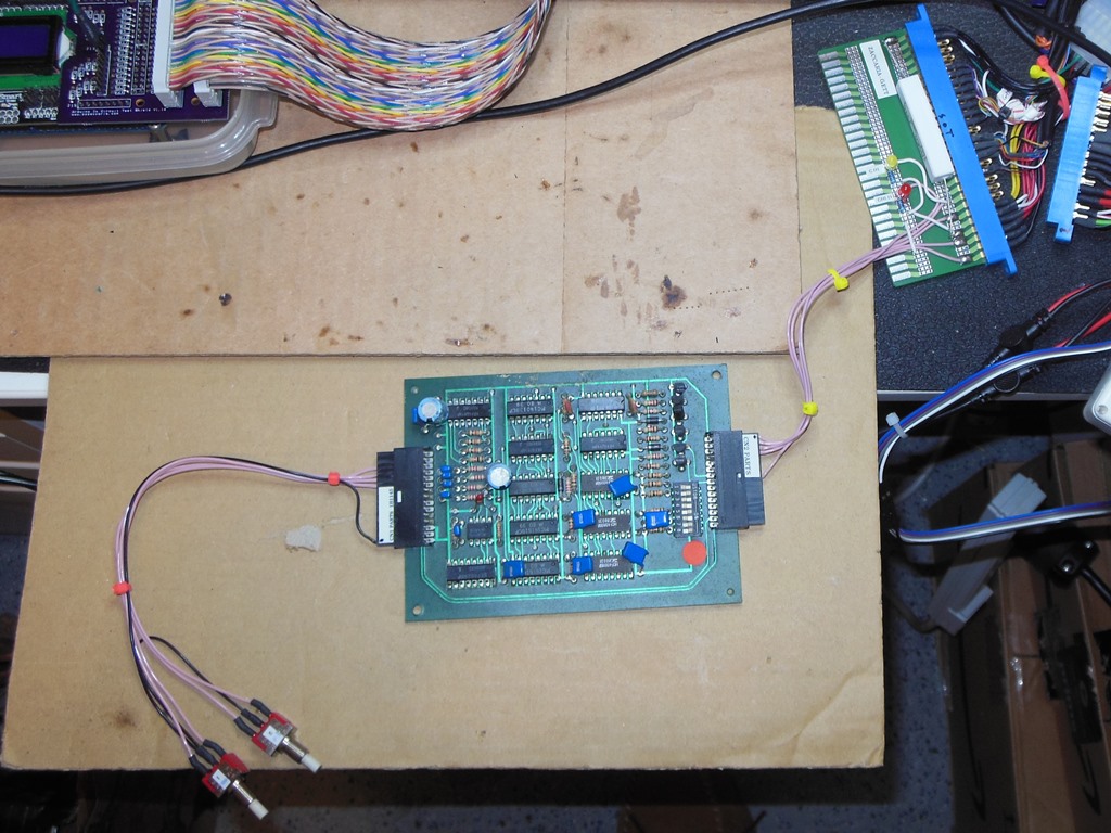
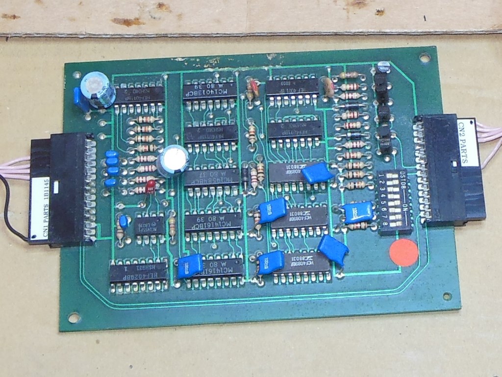
Since the credit PCB had been removed and the coin & credit wiring badly hacked I'd expected the credit PCB to be faulty, however on the bench the PCB tested OK. The DIP switches were set to one coin one credit on both coin slots.
 ,
,
|
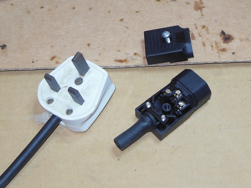
The UK plug was replaced with the usual IEC C14 socket that I'd settled on in the US for 240V games. As a German operated game it would have had a European plug originally but since it now had a UK plug it must have been in the hands of someone in the UK before me.
Initial power on with no game PCB revealed the marque light & monitor cavity black light not working however the monitor came on with a white screen.
 ,
,
 ,
,
|
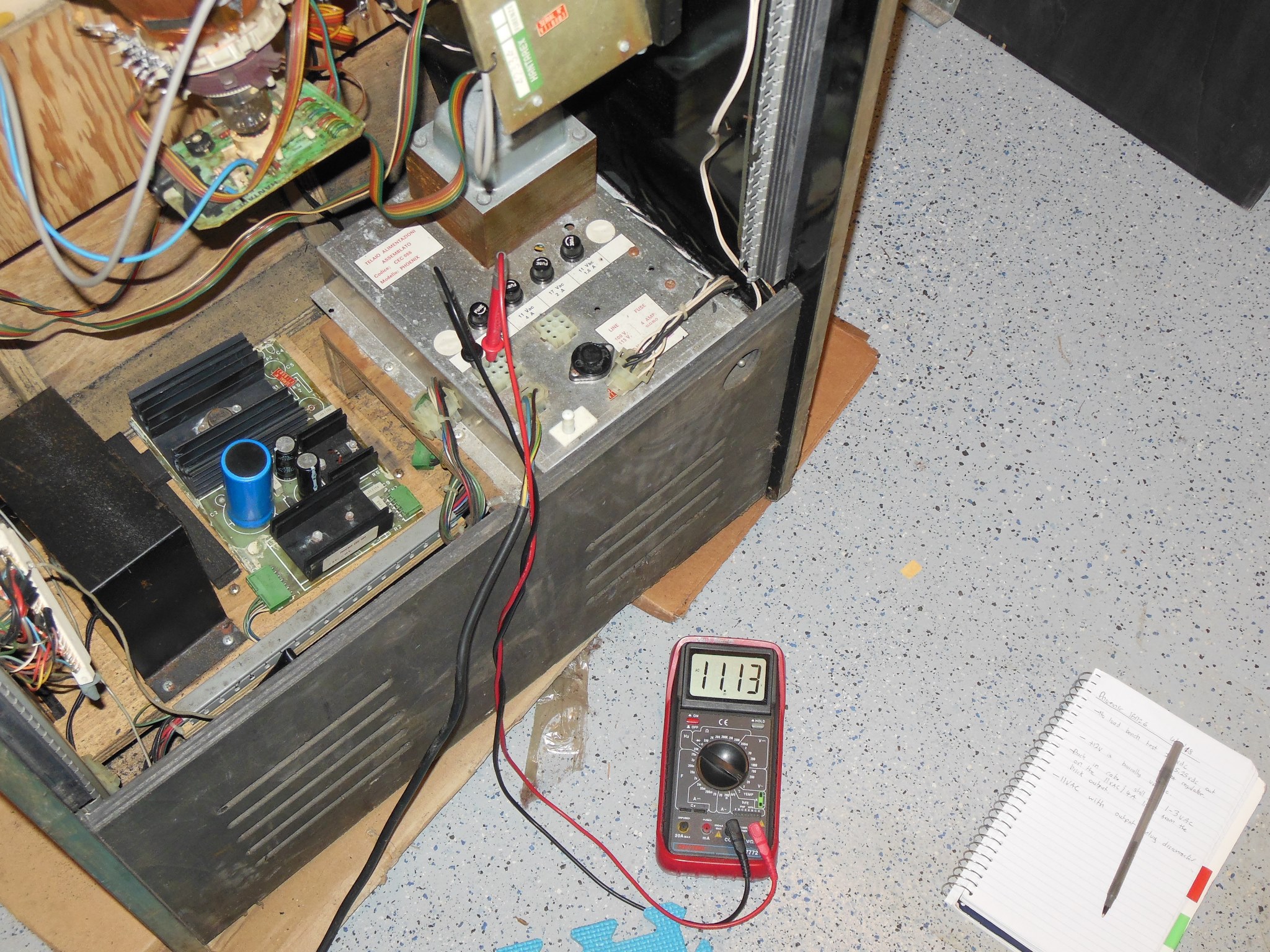
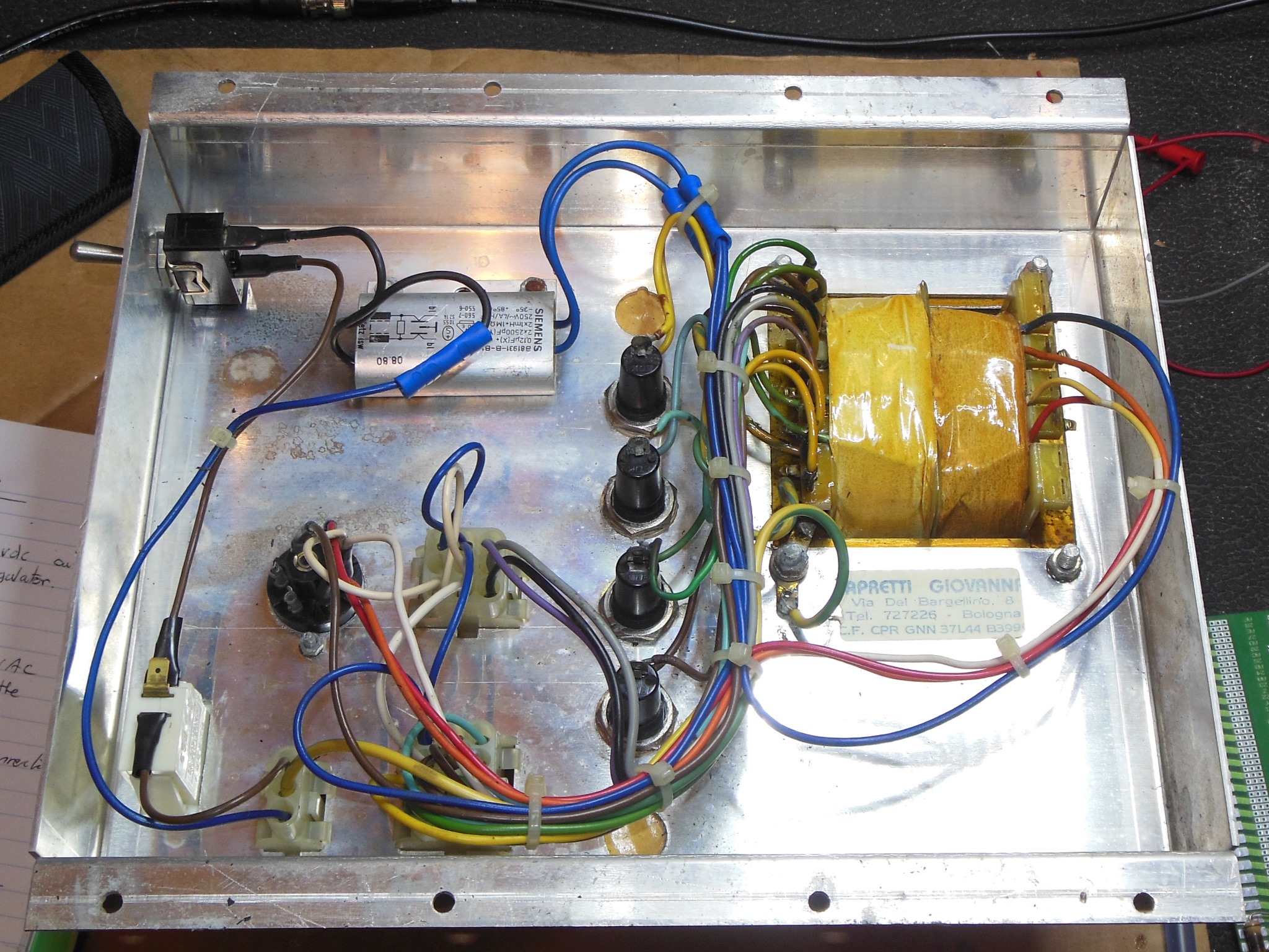
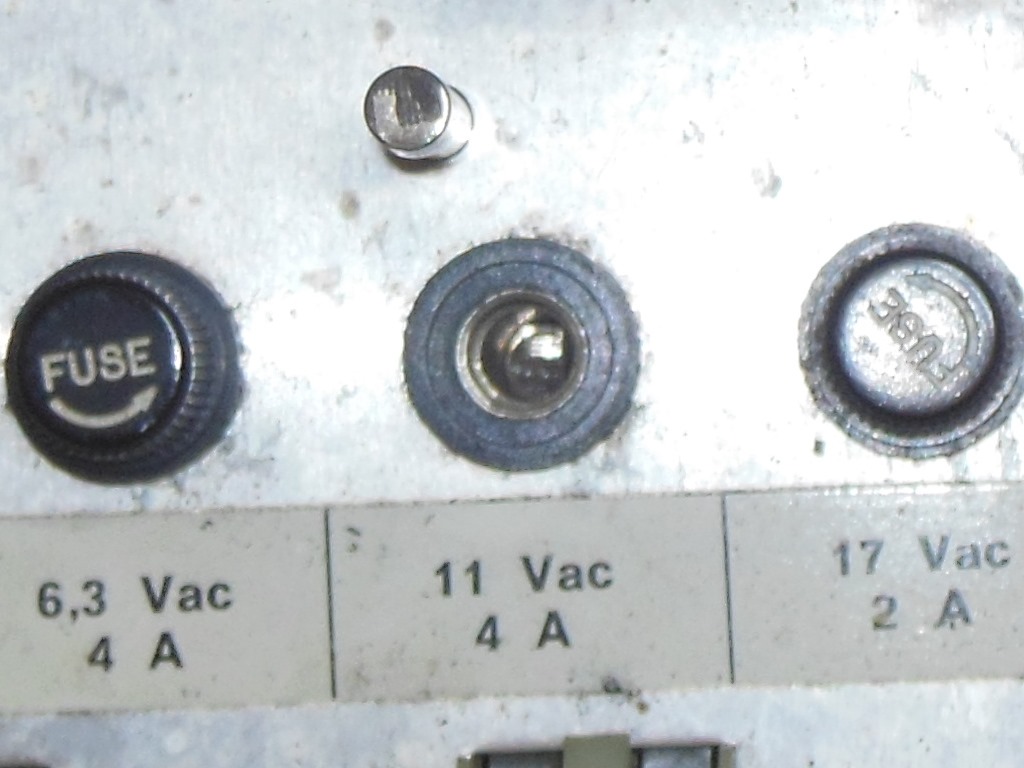
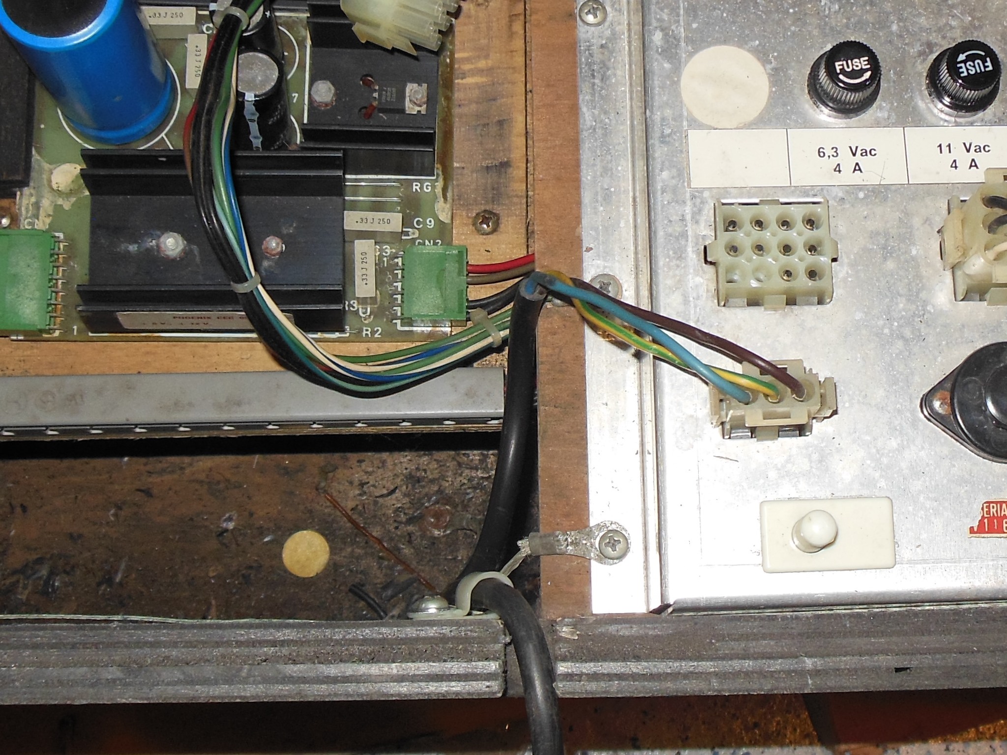
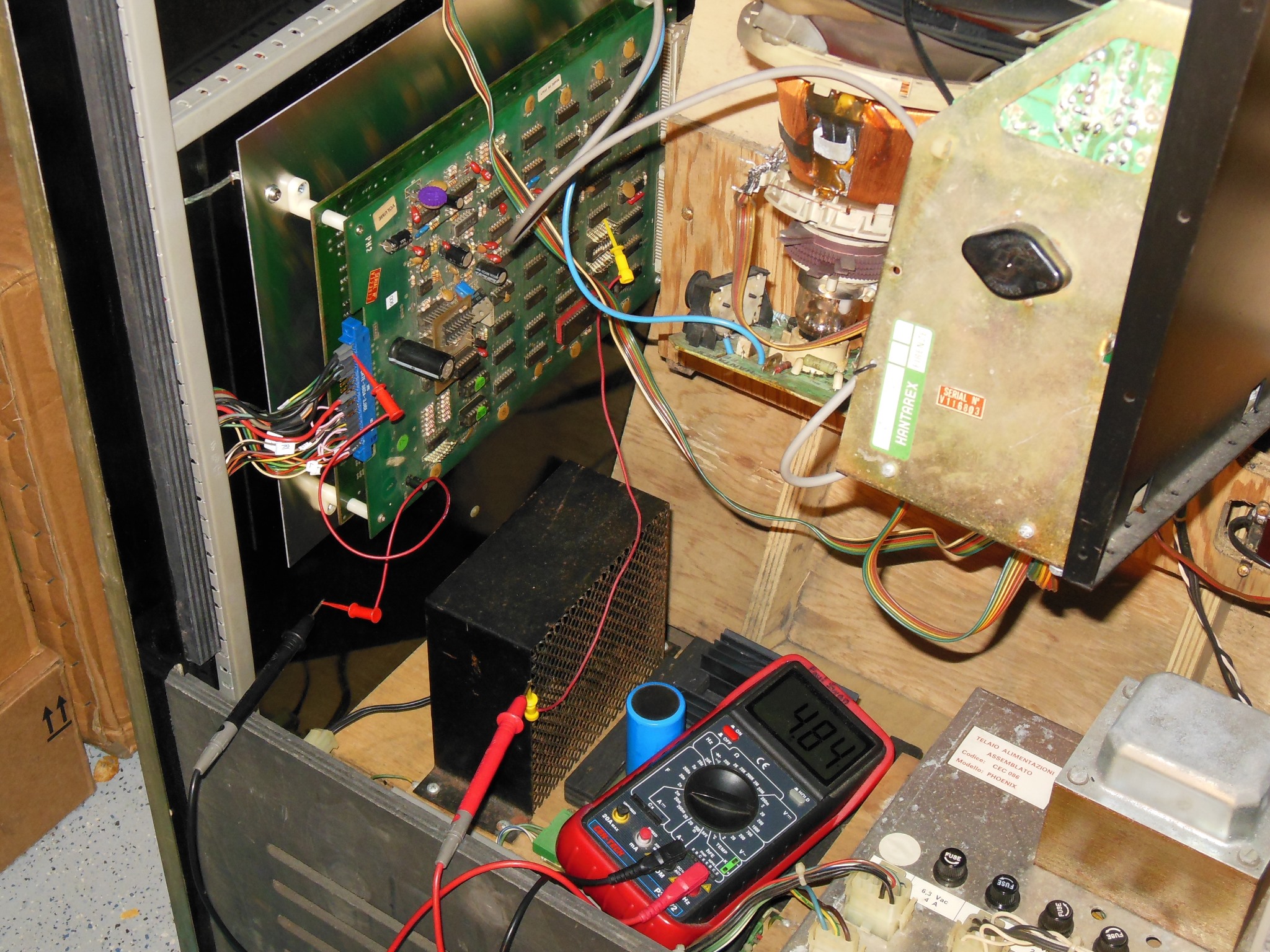
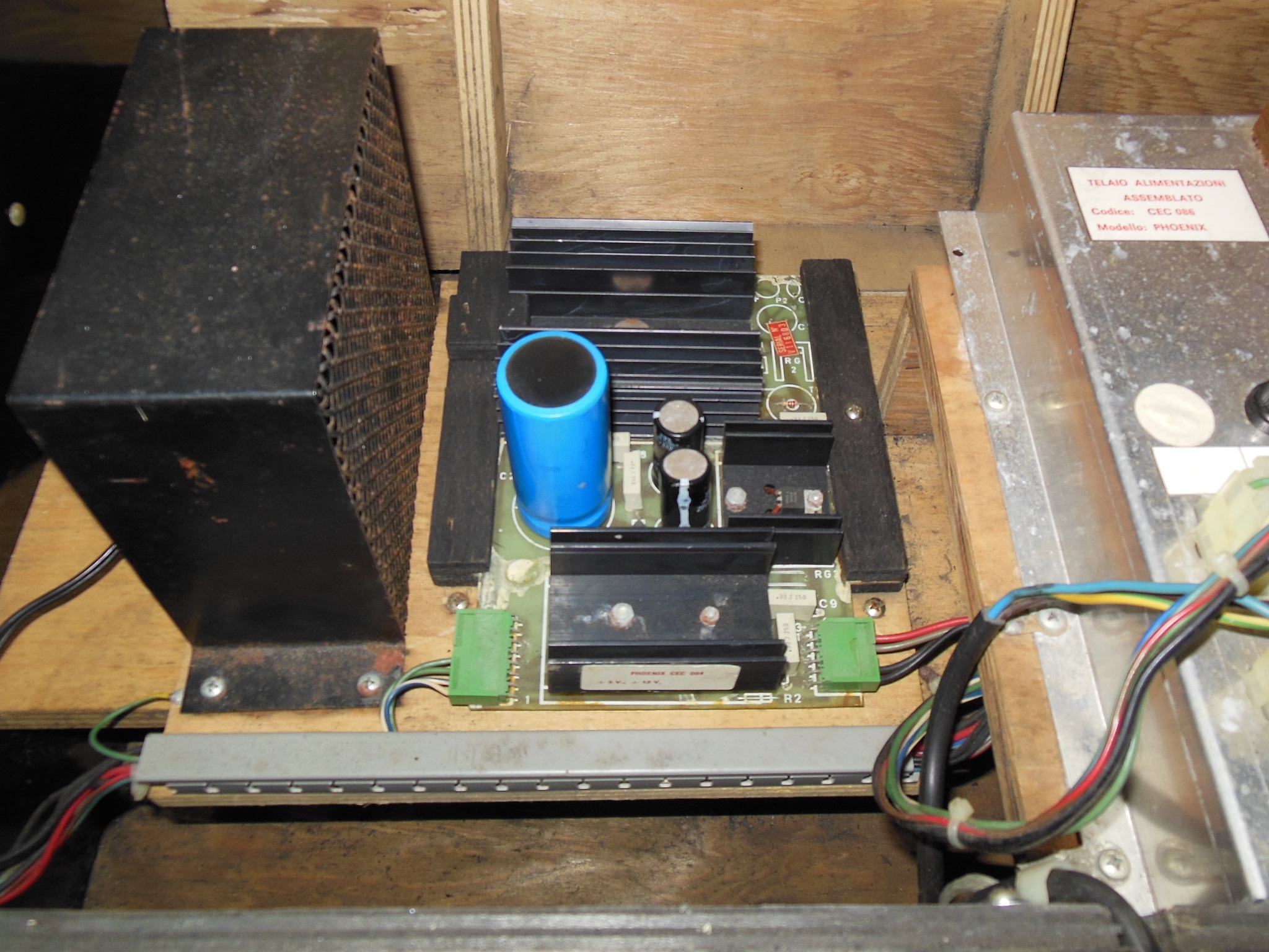
Initial testing of the power at the edge connector found the +5V was missing. Working back from the regulator PCB found the +11VAC input low at around 2VAC. The fuse on the power supply checked out OK. After unplugging the regulator PCB the 11VAC from the power supply measured OK. Suspecting the regulator PCB was bad I tested it on the bench expecting it to have some sort of short but the PCB appeared to be working OK. Looking again at the power supply, I noticed there was a change in voltage pressing on the top of the fuse holder so I suspected a problem with the fuse contacts. I removed the power supply for further investigation on the bench.
 ,
,
|
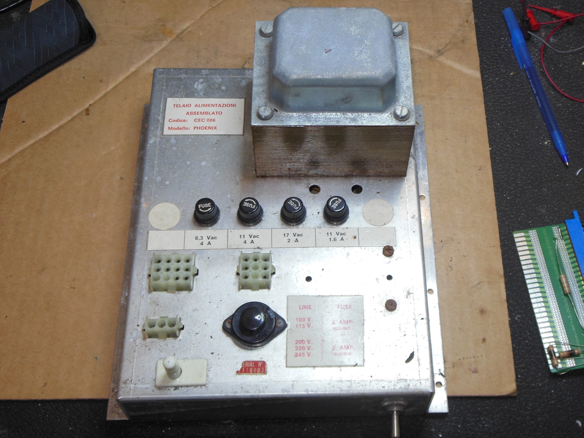
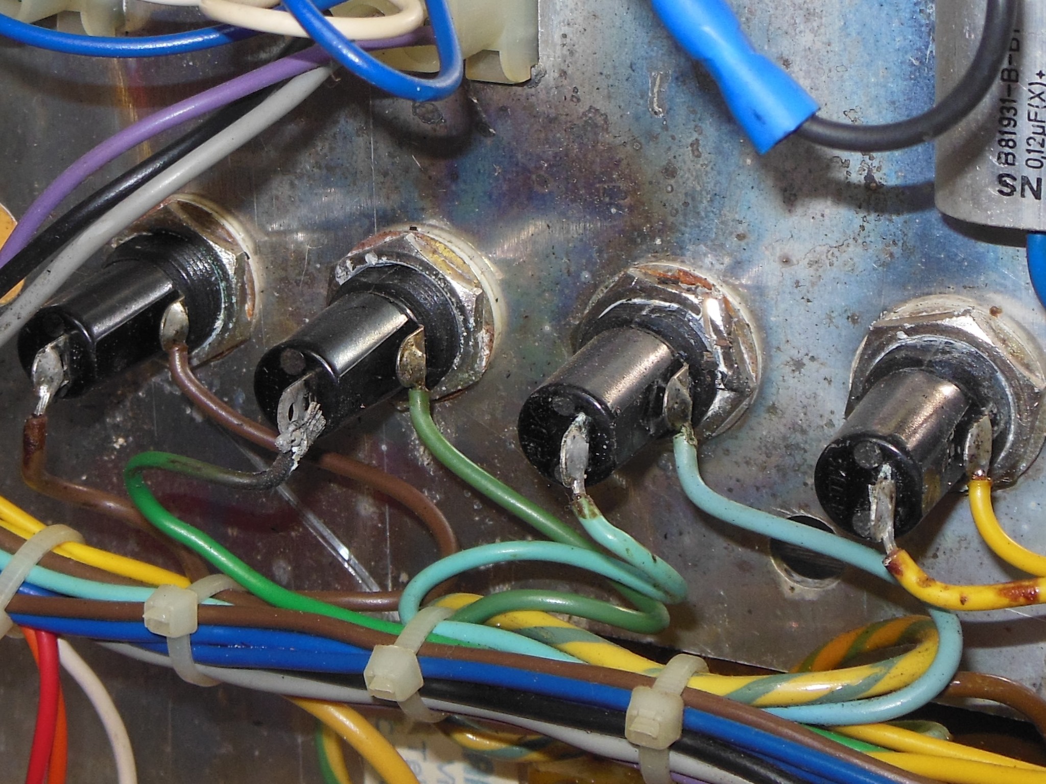
Examination of the bottom of the fuse holder found the solder joint between the pin & wire burned out. Both sides were cleaned up and the joint re-soldered.
The fuse holder contact with the fuse was still very poor - measuring open or high resistance - so I suspected the heat from the dry joint had damaged the fuse holder. I had no spares to hand but they were readily available from eBay for a few dollars.
 ,
,
 ,
,
|
The Zaccaria Phoenix manual shows the coin door wiring. Some of the wires had been trimmed back that necessitated some extension splices to reach back to the connector.
 ,
,
 ,
,
|
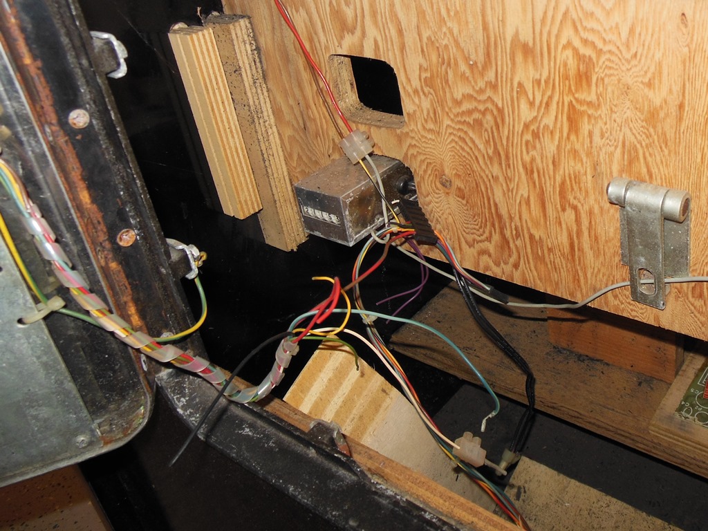
The credit PCB input connector was spliced back together. The credit output connector had one cut wire and the coin counter also needed to be spliced back into the wiring.
|
The degauss button had also been cut out (I suspect to be used as a credit button instead) that was spliced back into the degauss wiring.
|
The new fuse holders for the power supply arrived and the burnt fuse holder was replaced. With the new one fitted there were no further issue with the fuse contact.
 ,
,
 ,
,
|
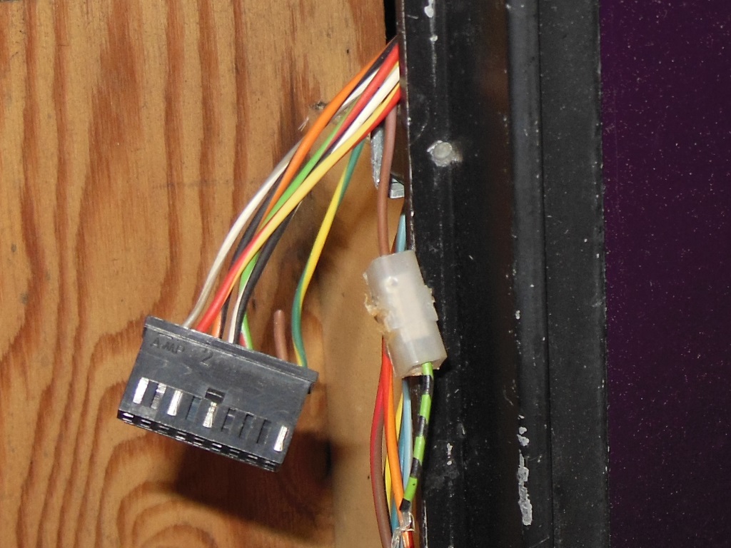
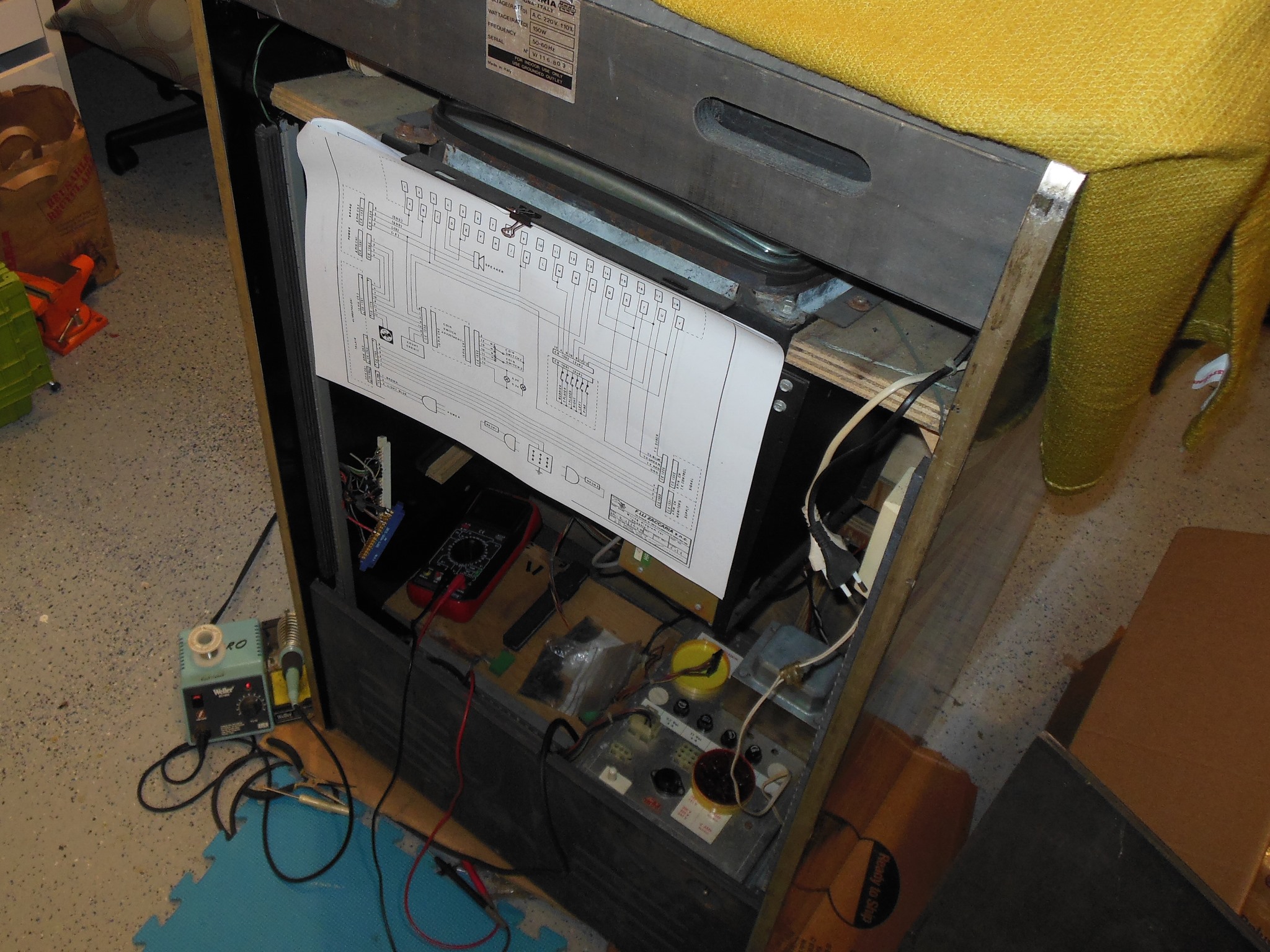
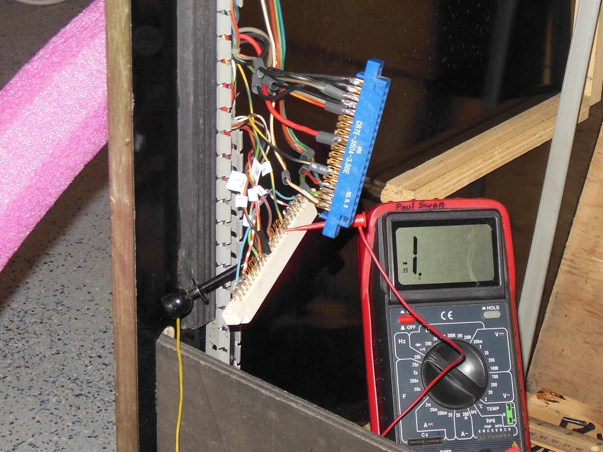
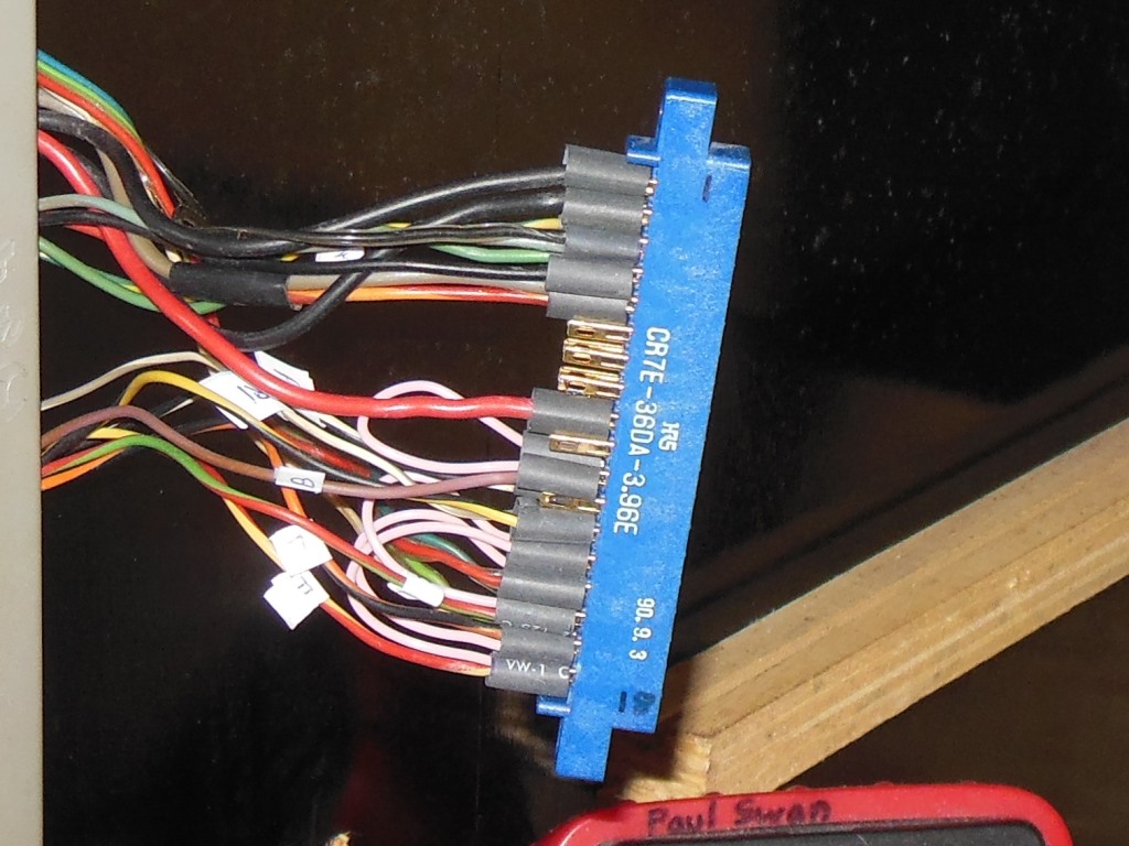
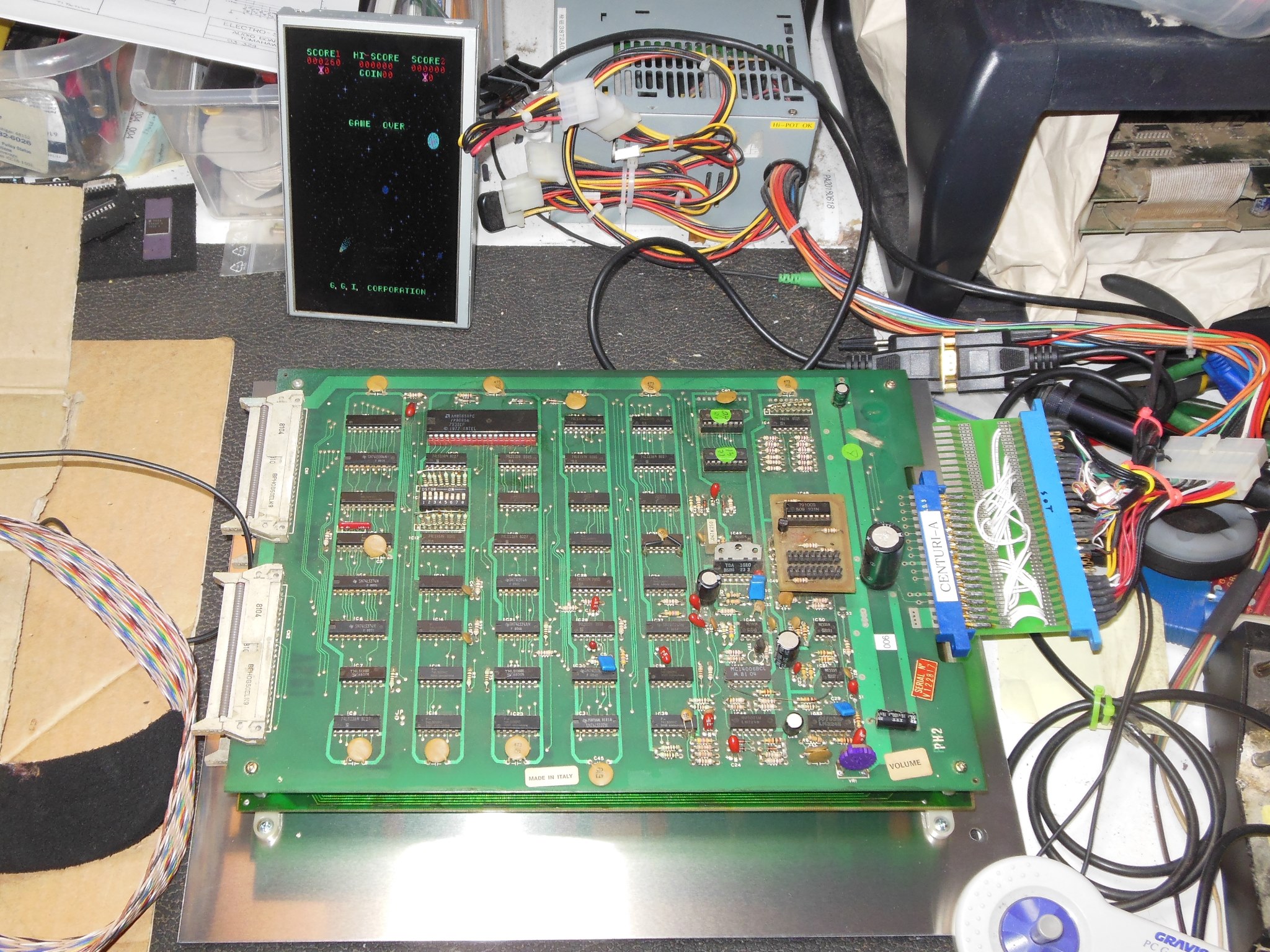
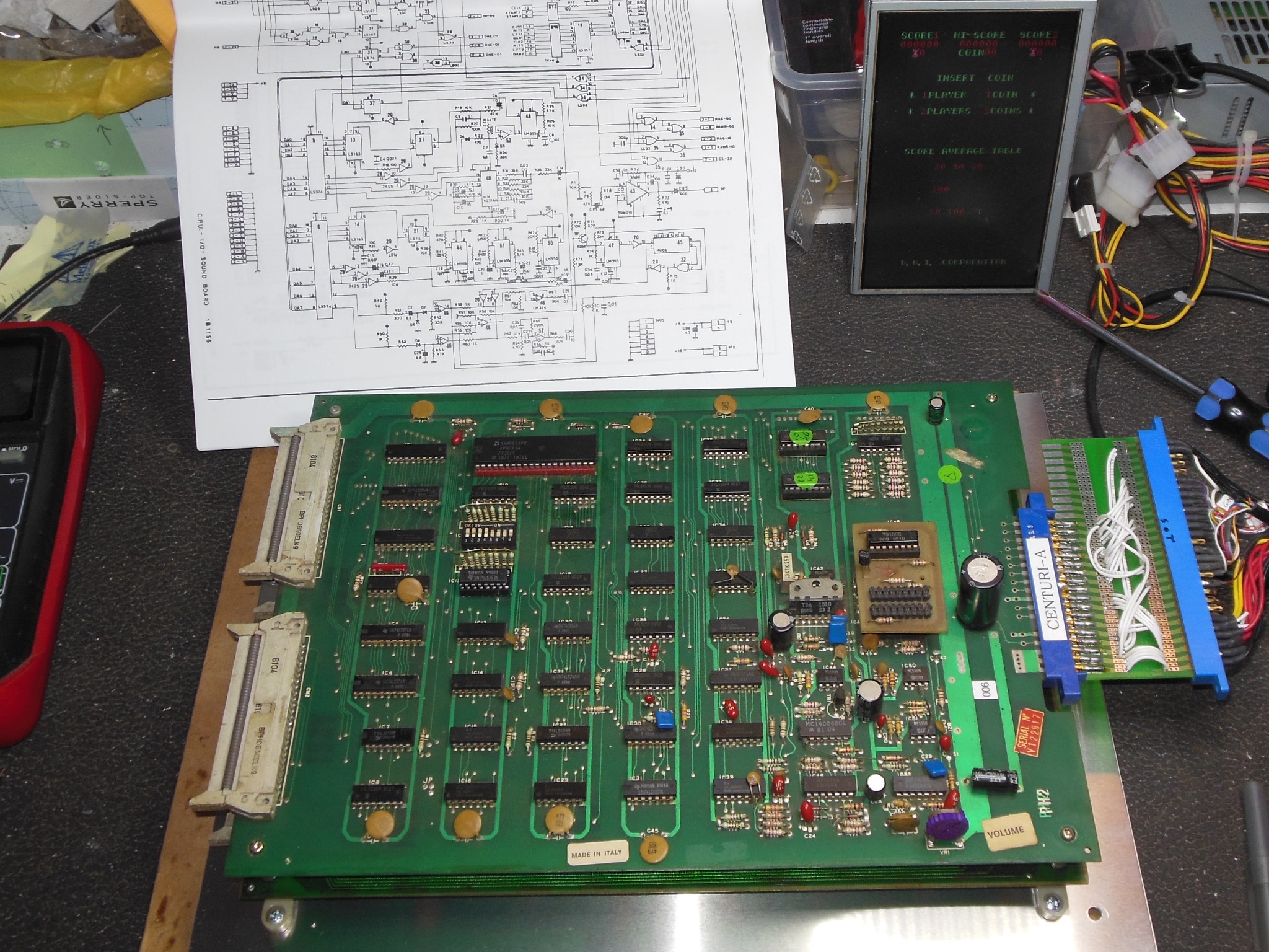
The game PCB edge connector had been replaced with a larger one as part of a conversion to a different game. The manual wiring schematic and a multimeter were used to figure out the wiring and gradually migrate from the old connector to the new Phoenix connector. Power & video were straight forward, the control panel inputs needed a bit more investigation.
|
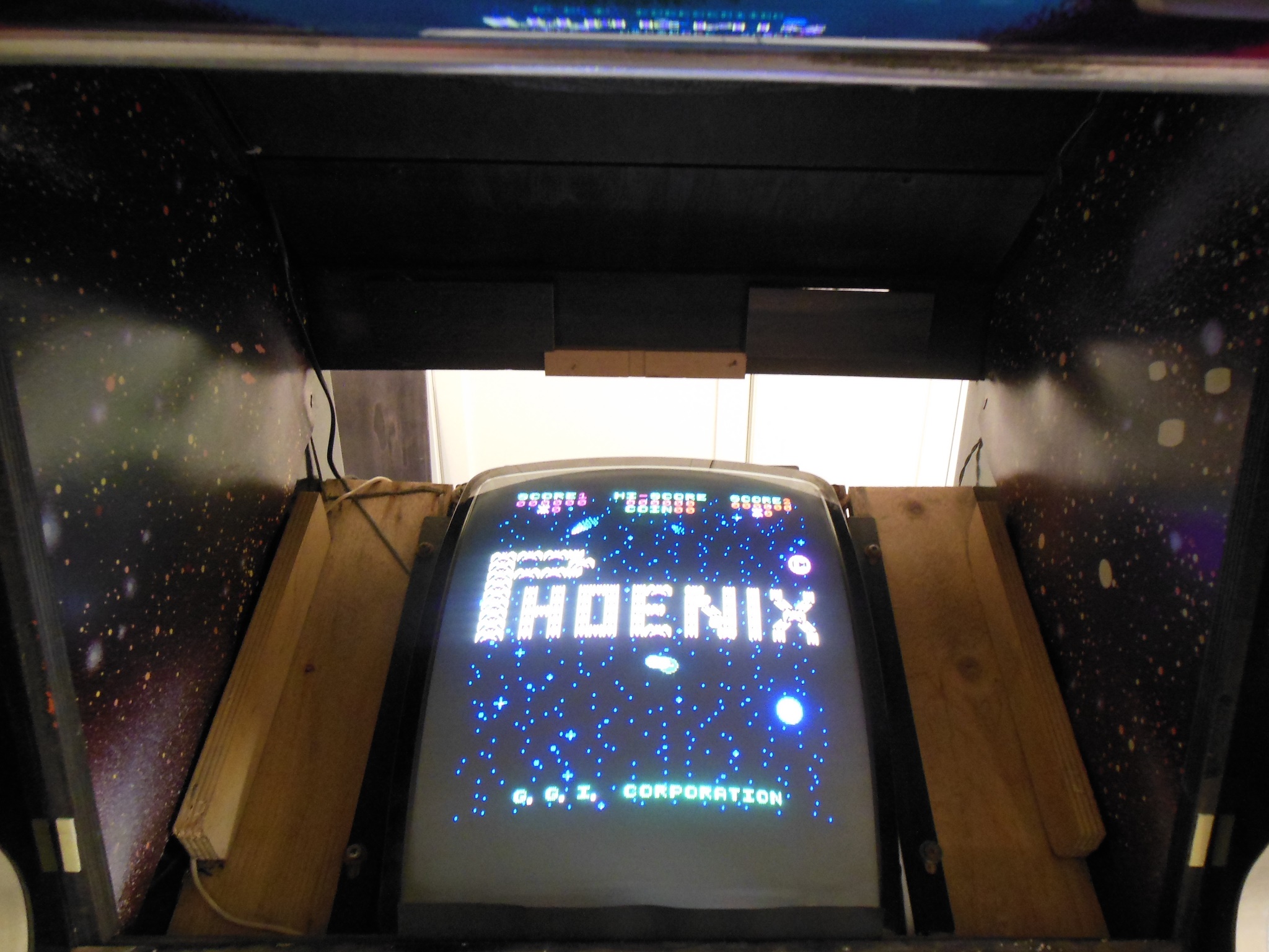
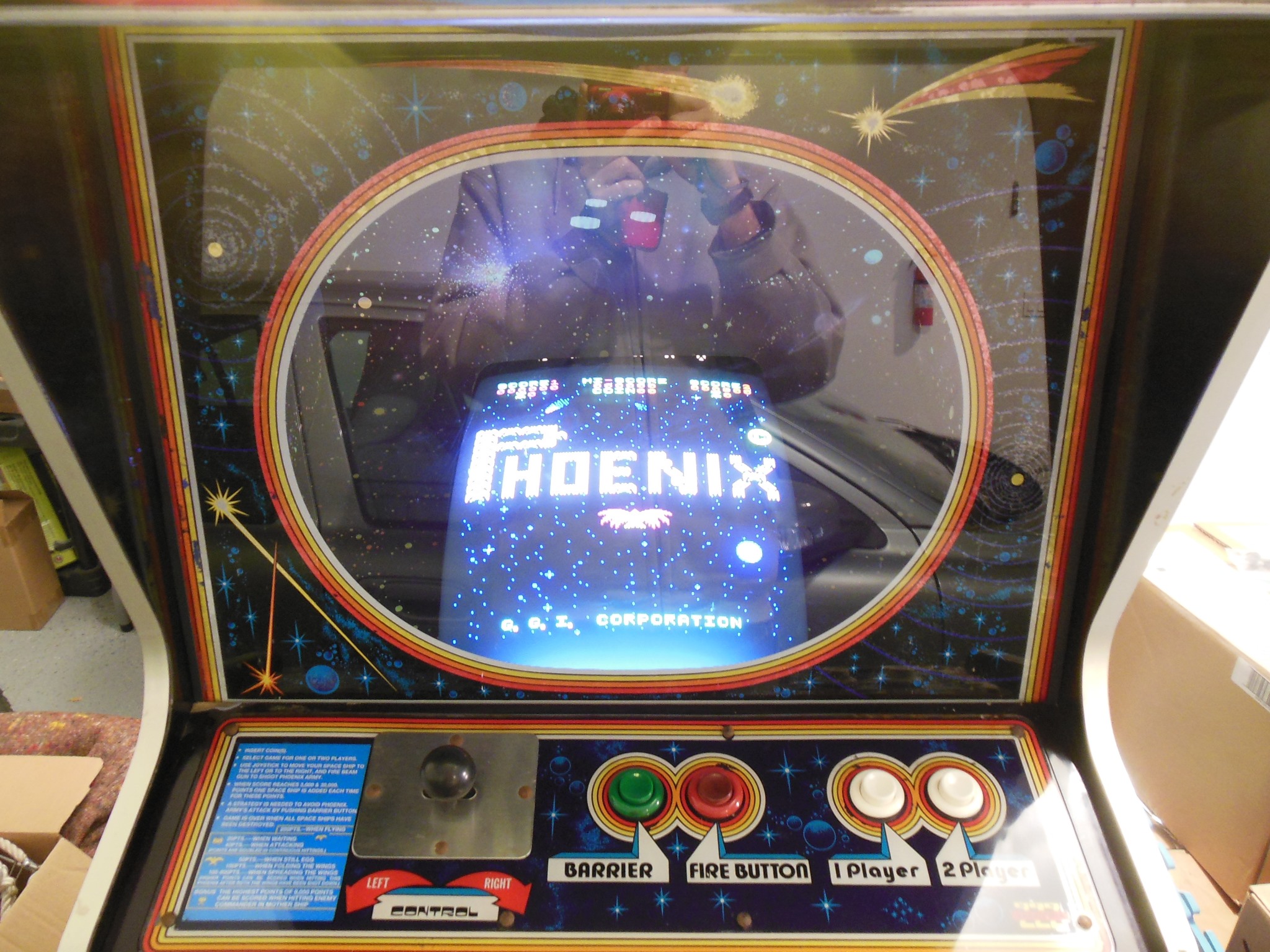
I held off on shrinking the heat shrink until the game was verified working. With a Phoenix PCB fitted first power on revealed a bright out-of-sync picture.
|
A tweak of the sync pot on the monitor was enough to lock the picture. The picture was out of adjustment that I left as is to tackle after the monitor chassis had been cap kitted.

|
The credit PCB was plugged in and tested in the cabinet - both coin switches registered one credit in the game and it was fitted back into its slot.
|
The marque light wasn't working and even though the old tube looked quite burned on one side it metered out OK. A new starter was all that was needed to light it up.
|
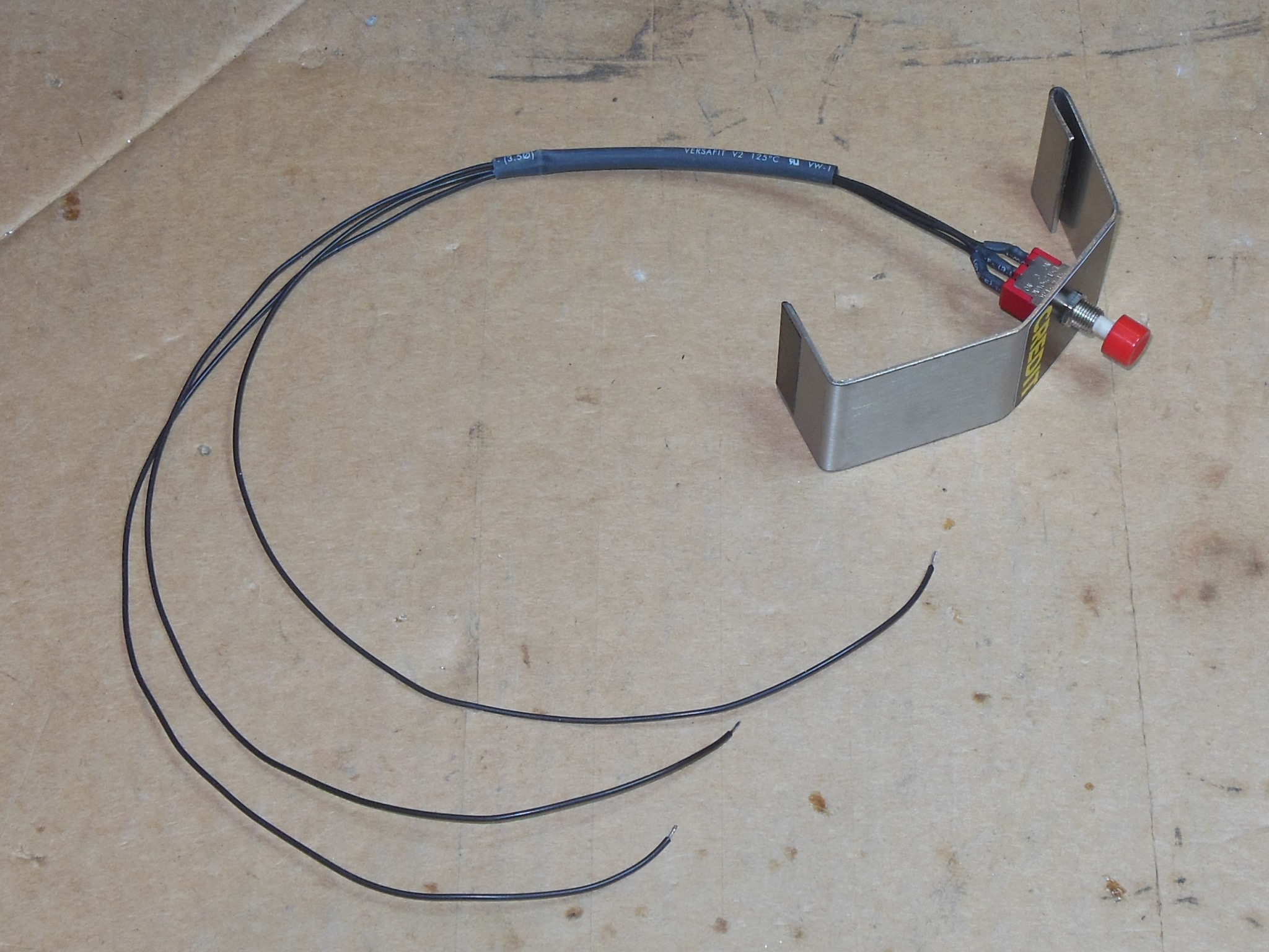
I assembled a 3-way (Normally Open, Common, Normally Closed) credit button ready to fit to the coin door.
At this point the Phoenix restoration was paused to focus on Northwest Pinball & Arcade Show preparation.
|
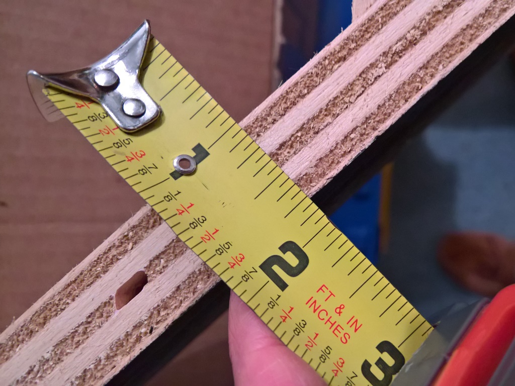
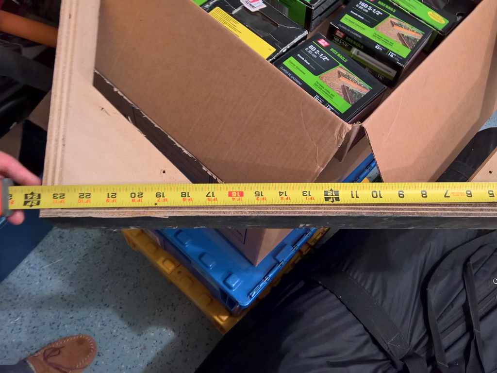
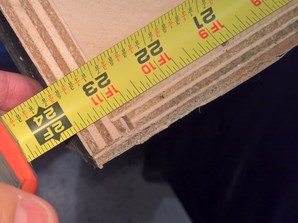
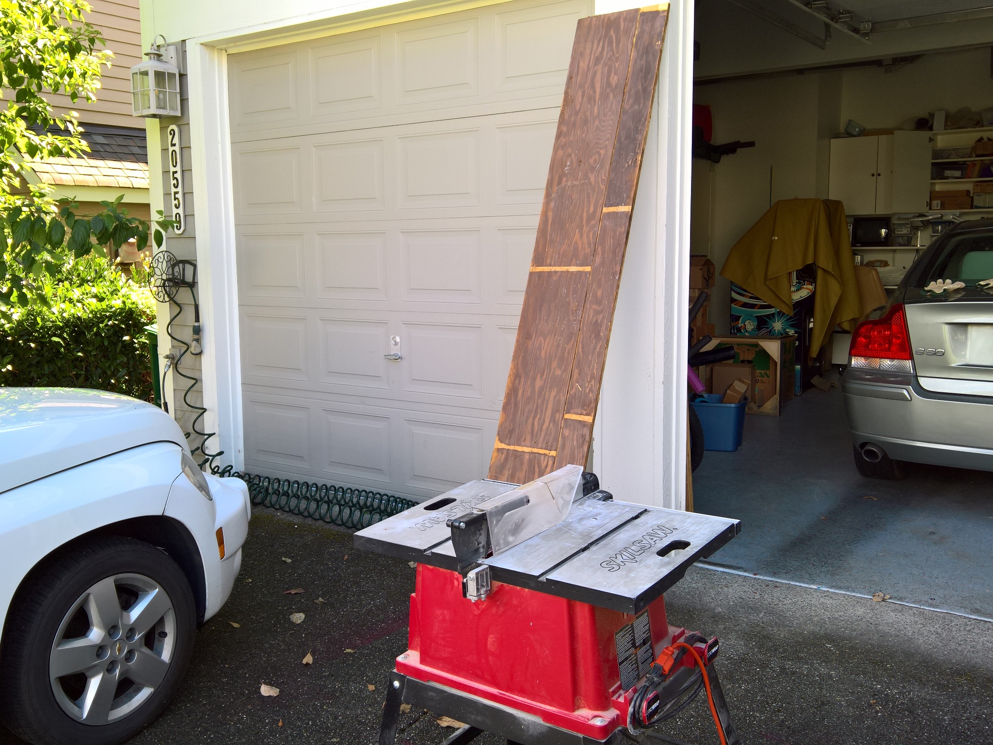
The sample base from another machine was measured up to determine the wood required to make a reproduction. The plywood was 3/4" thick 5-ply with finishing layer on both sides and needed to be at least 24" long and 5" wide for the skirt.
A trip to Home Depot found their stocks of plywood mostly 11/16" thick with only one variation of birch plywood available in 3/4" thick, so I decided to see what I had left over from domestic projects first.

|
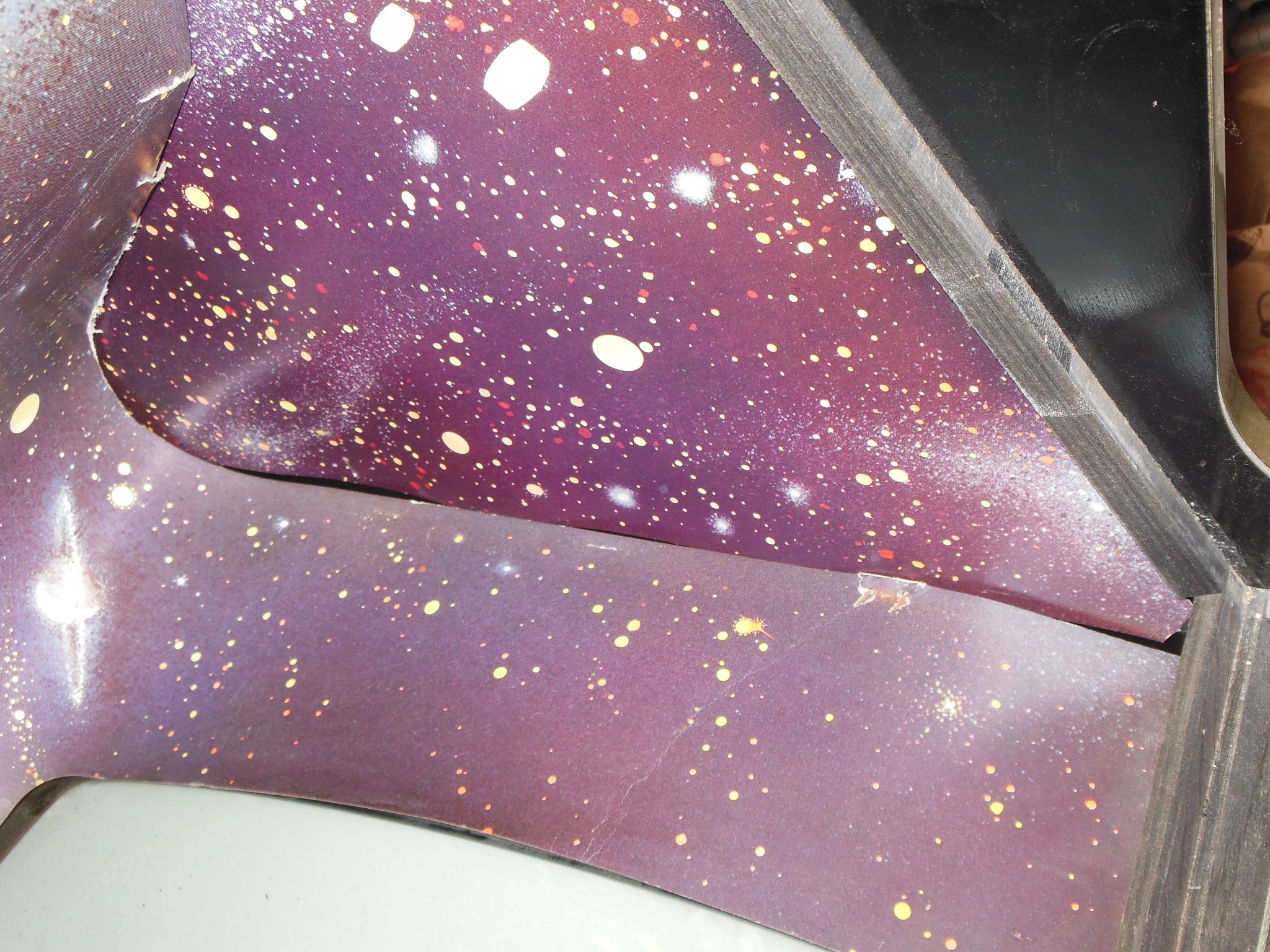
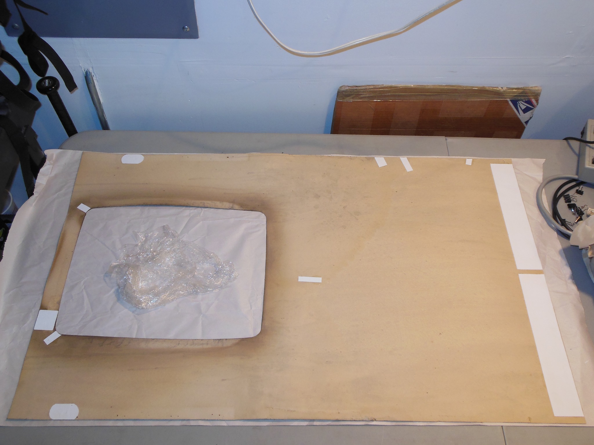
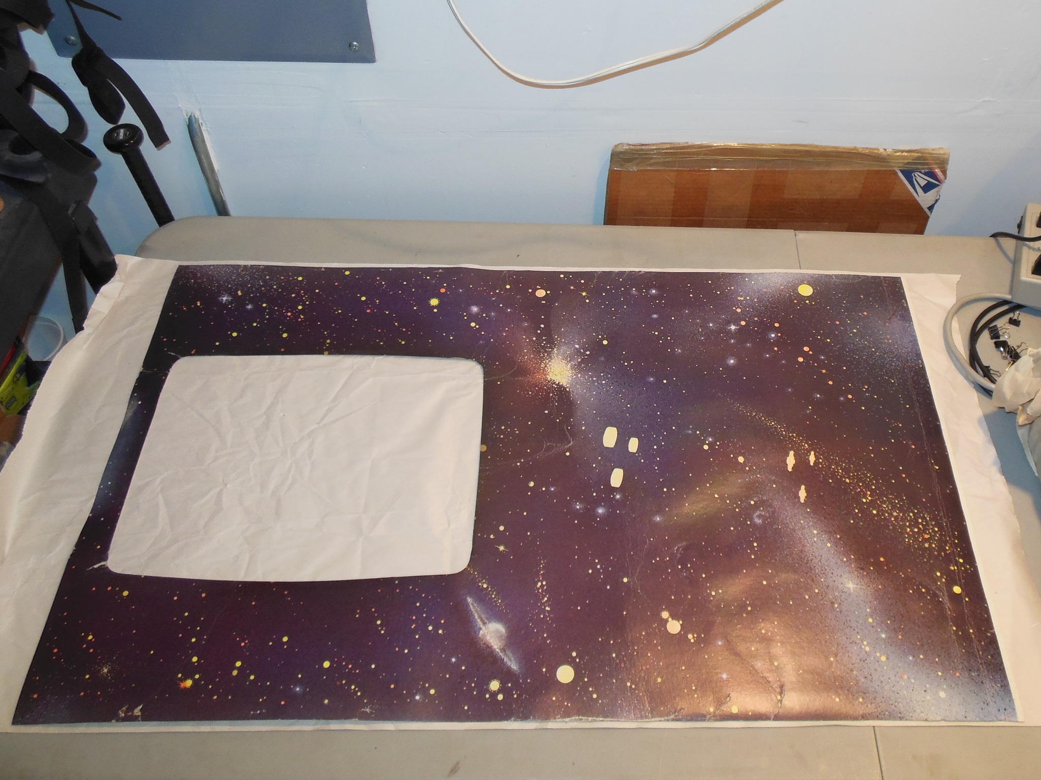
The monitor surround was a bit battered with a few tears. The monitor glass artwork was also damaged, particularly along the edges as a result of missing beading along the sides the disintegration of the foam spacers that had allowed the rough wood side rails to scrape the paint.
|
The surround had already been torn up from the side staples so only the top staples needed to be removed. Unlike other later cabinets there was no slot in the front glass side runners to be able to slide out the surround, necessitating an awkward flatten out and twist diagonally maneuver. I can see why the surround was beat up given the awkward removal :(

|
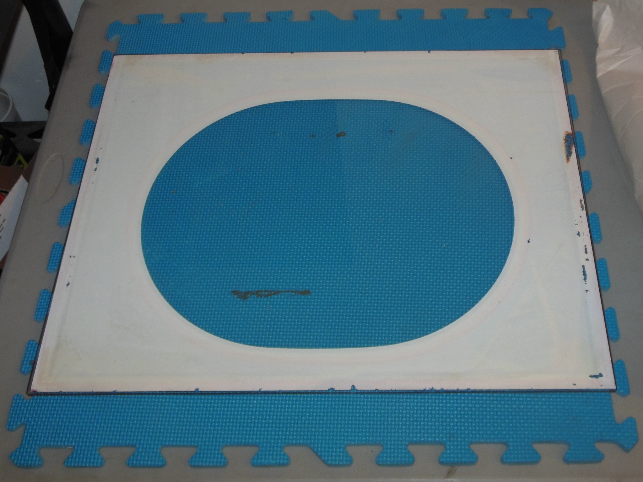
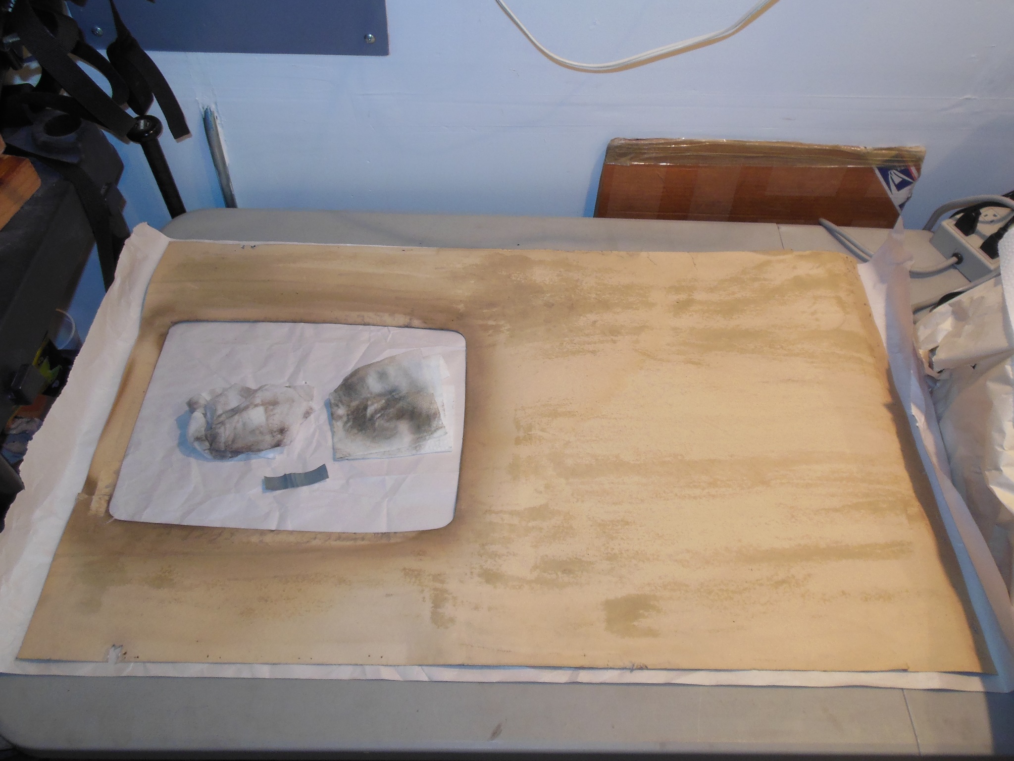
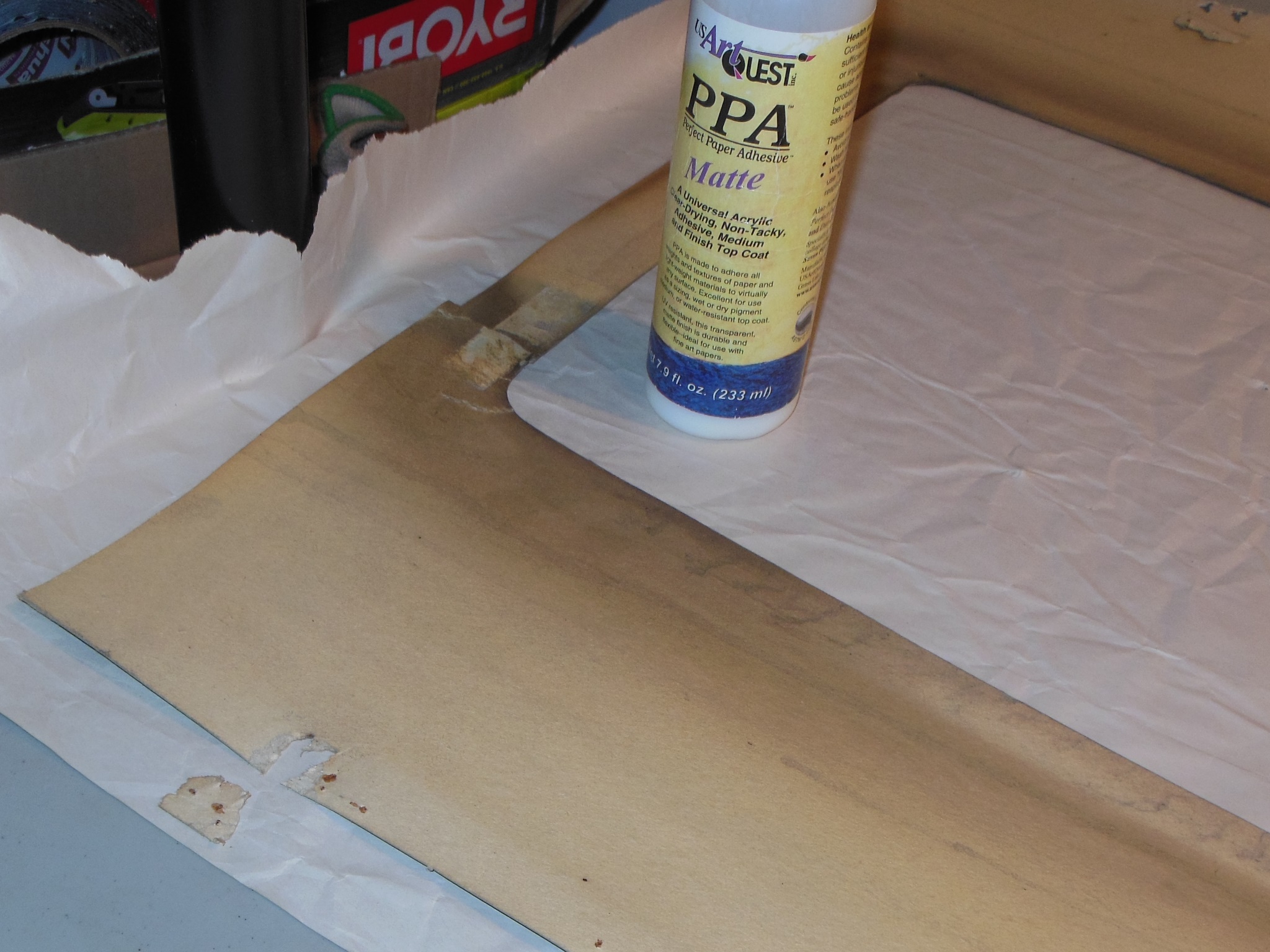
The surround was wiped down with a damp cloth and then set to flatten out for a few days.

|
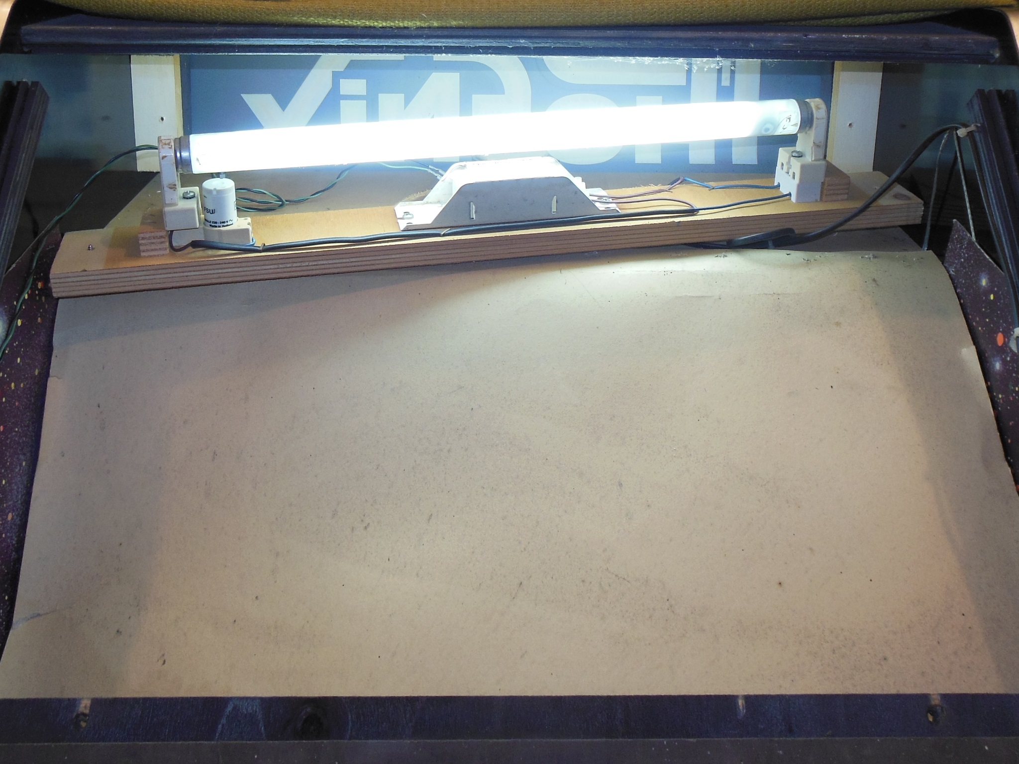
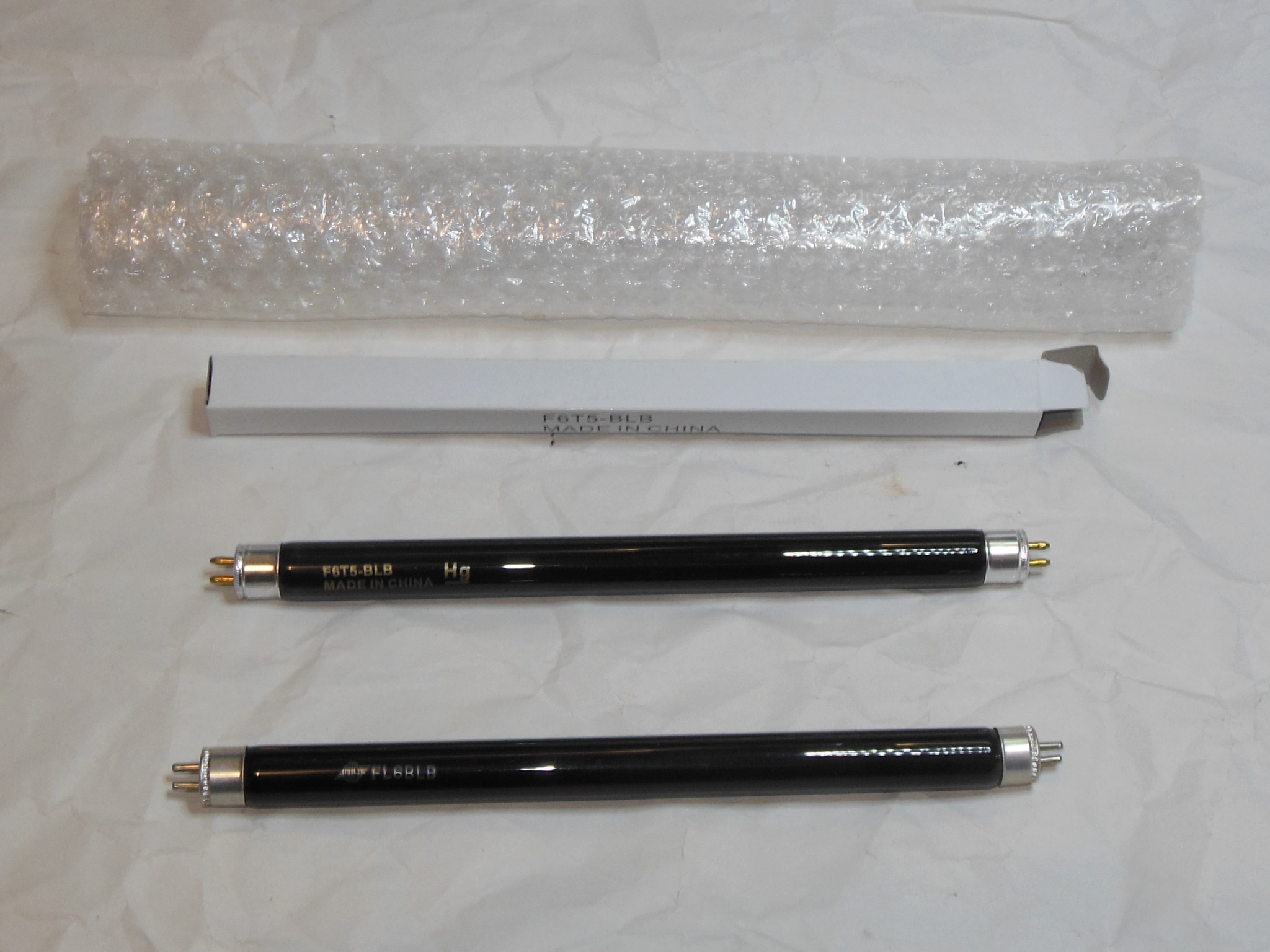
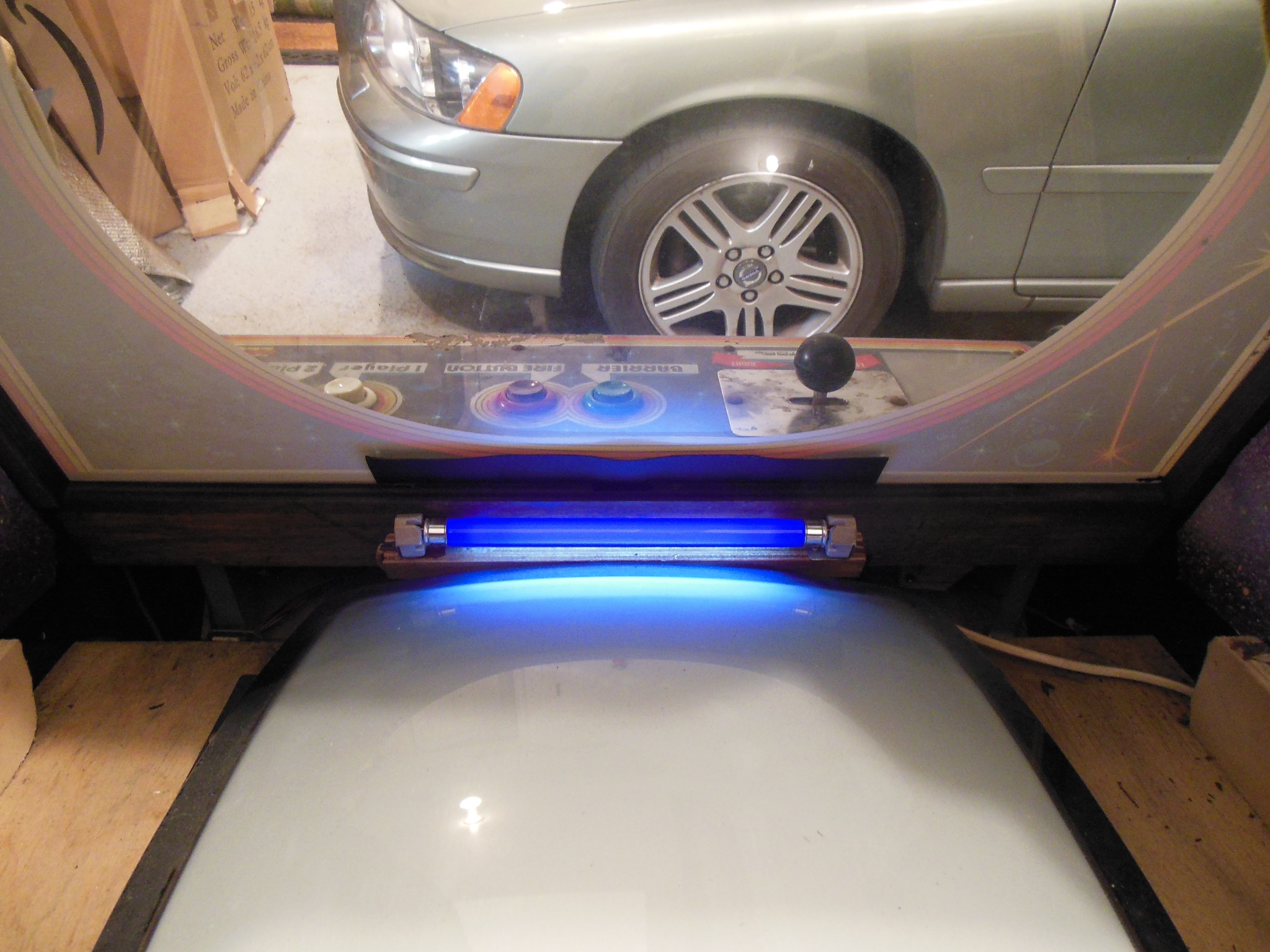
The blacklight for the monitor cavity wasn't working. One the bench the tube heaters tested open and new F6T5-BLB "Black Light Blue" bulbs were ordered from eBay. A new tube and starter was all that was needed to fix the blacklight.

|
The missing cord grip for the power cord was fixed.
|
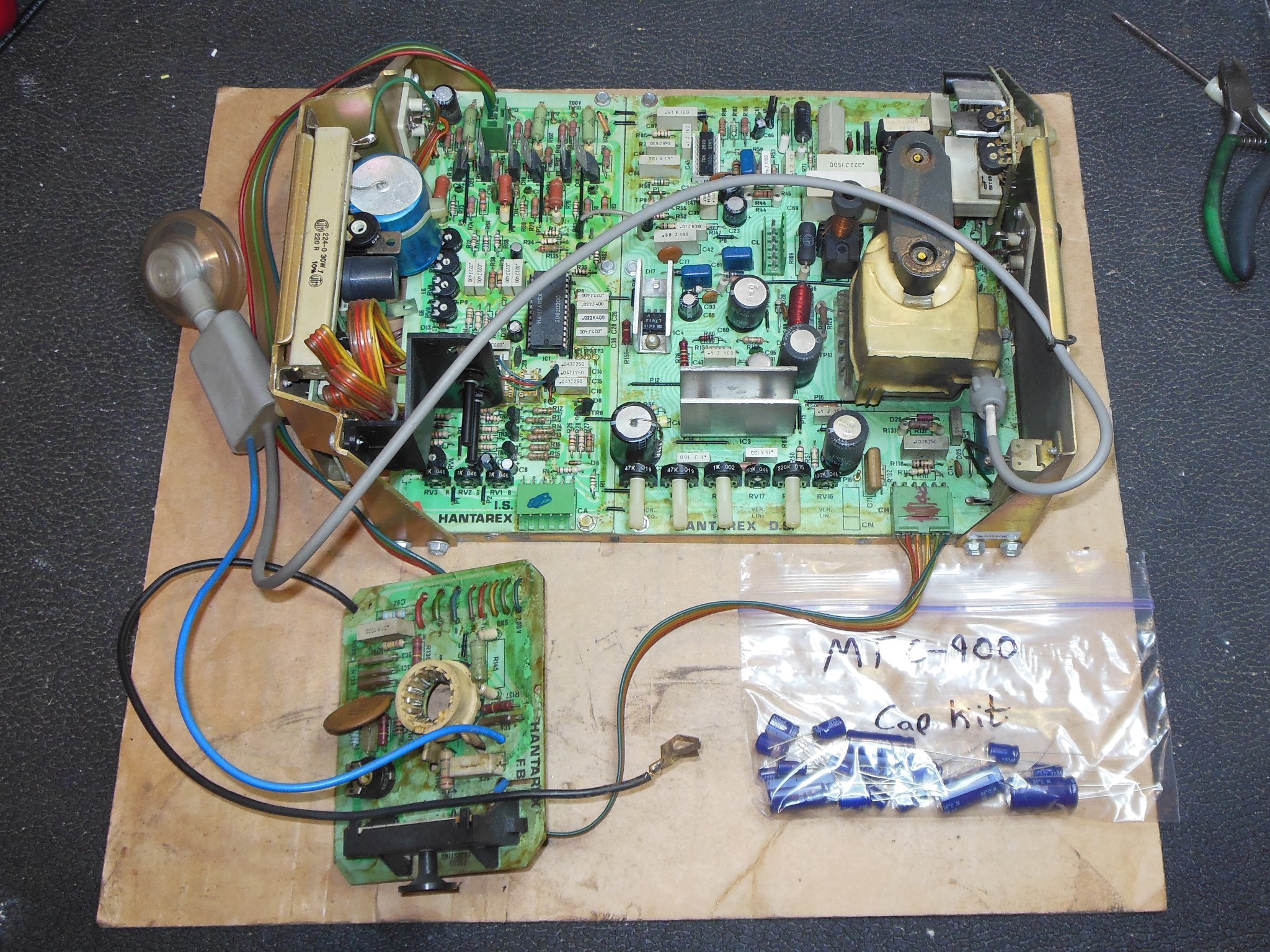
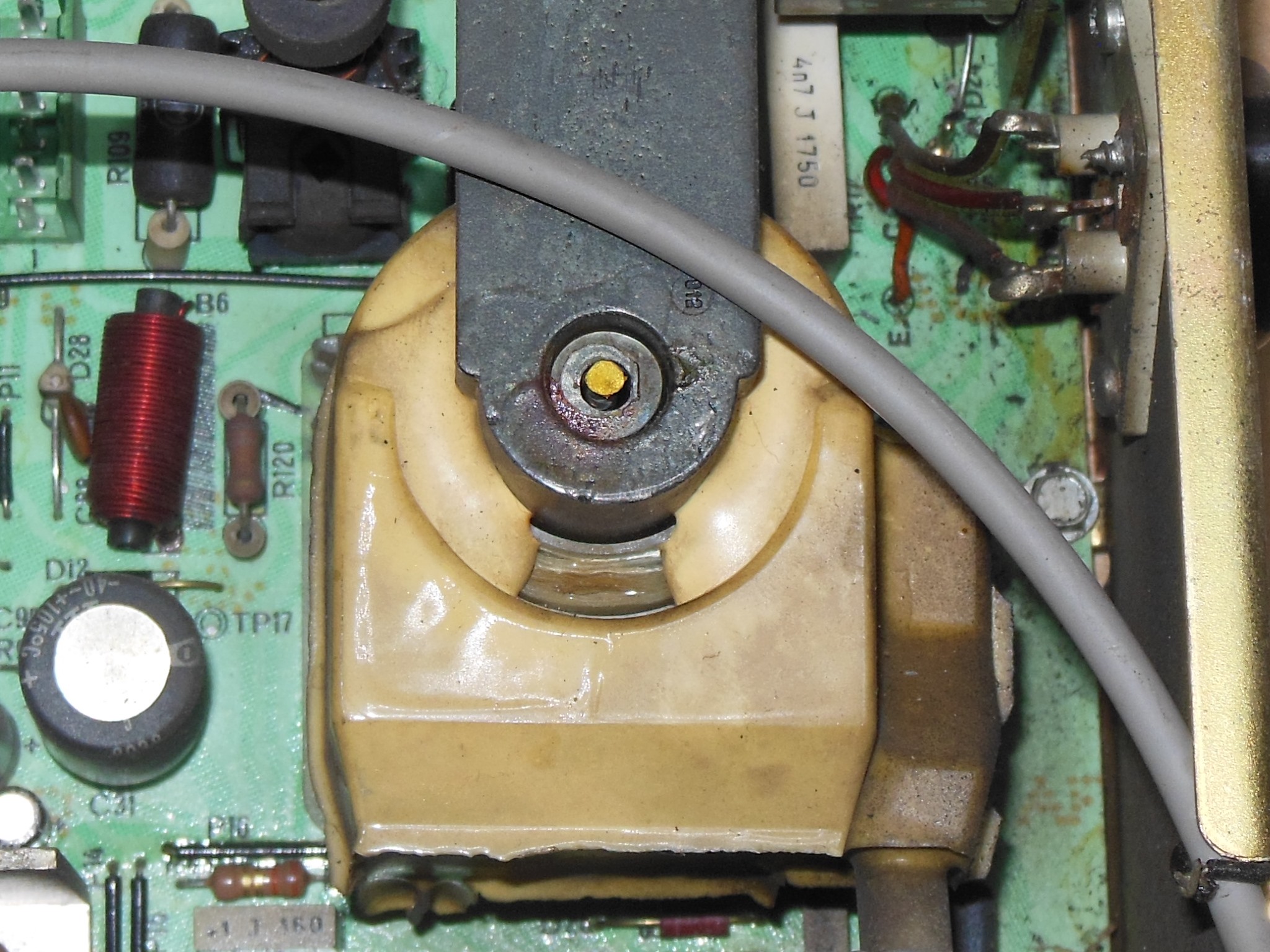
A cap kit was fitted to the Hantarex MTC-900 chassis using a previously assembled DIY kit. This was a very early run of the MTC-900 chassis with simpler metalwork and incompletely sealed LOPT. The 900 LOPT is generally very reliable - the only failure I'd had so far was on a similarly unsealed example. Therefore I expected this one to suffer the same fate eventually :( I thought about sealing it but didn't have a good, safe, material known for this purpose and thus didn't want to risk it.
|
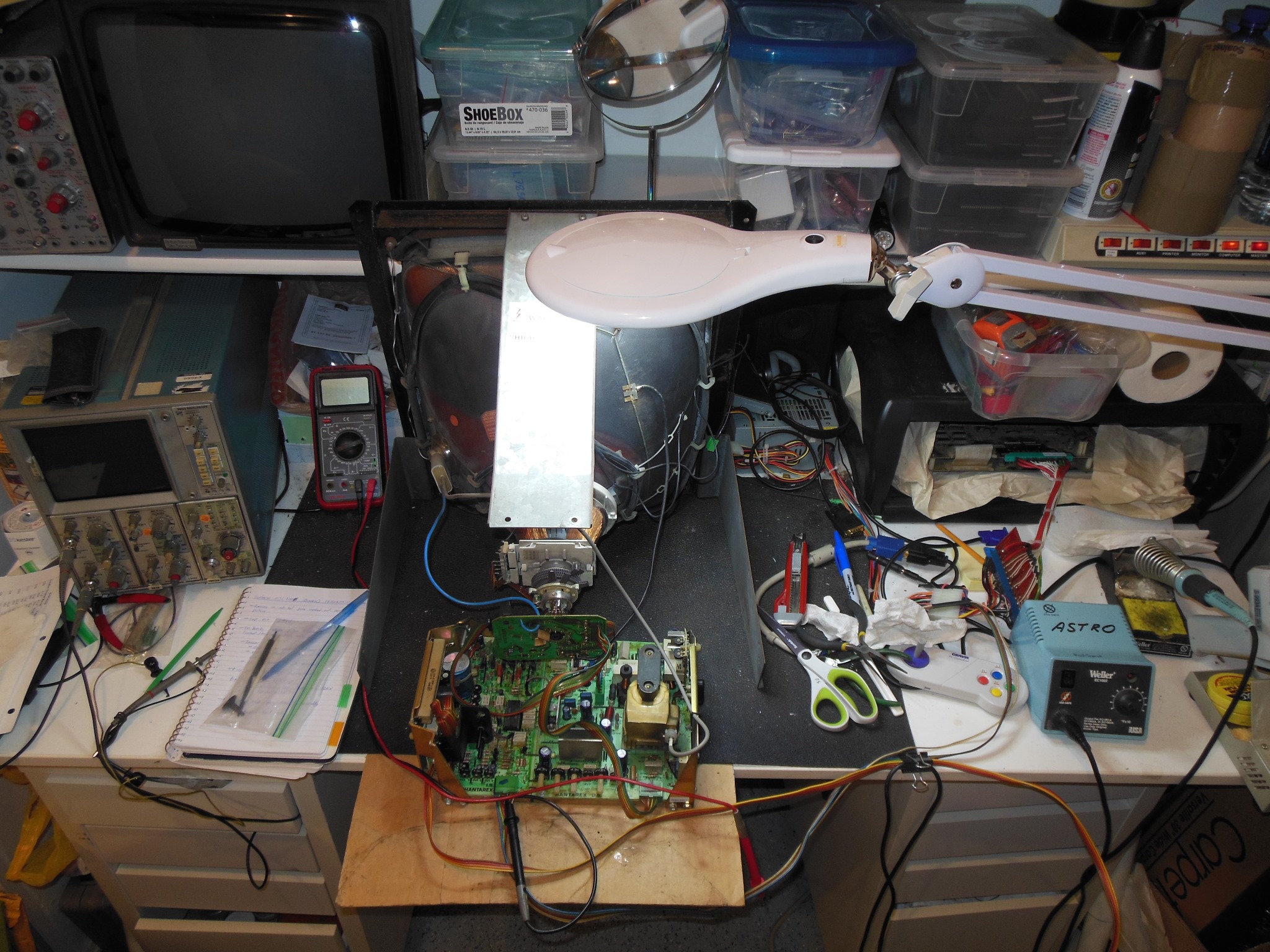
Several hours of bench testing didn't encounter any failures and the picture quality was good on the test CRT. The chassis was ready to go back into the cabinet.
|
|
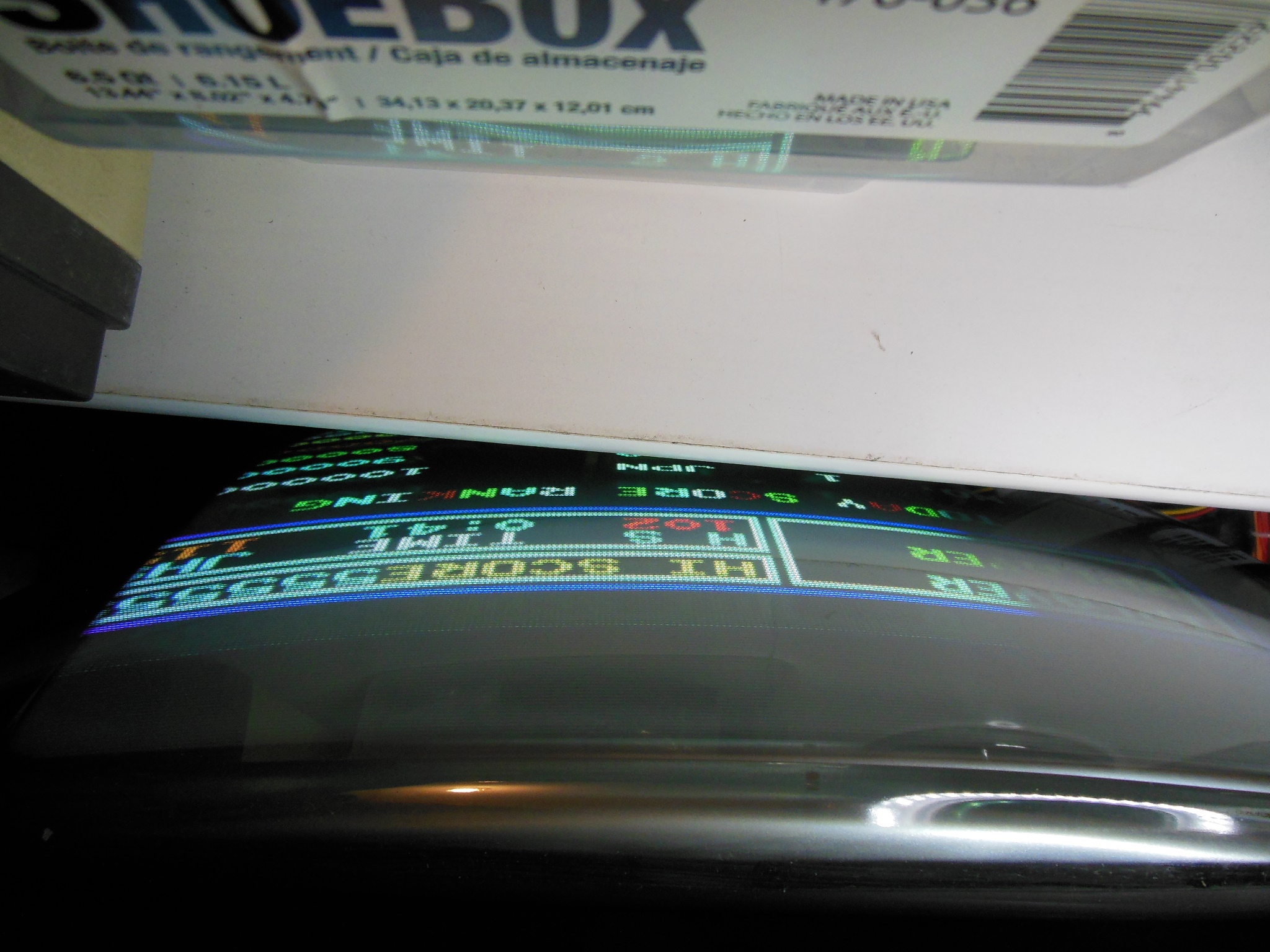
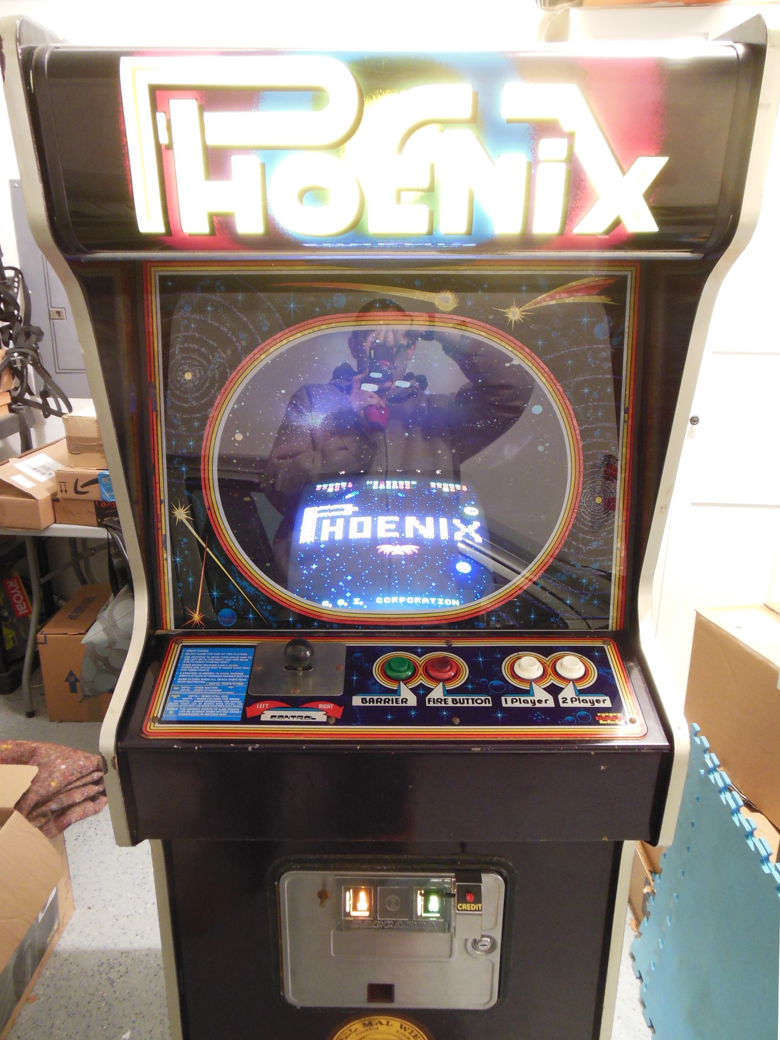
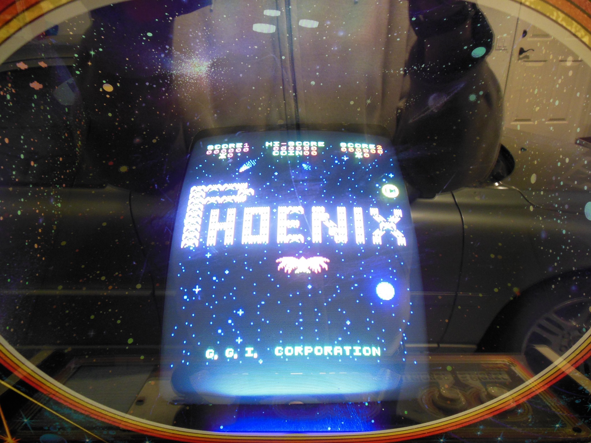
The cabinet was vacuumed and cleaned up. The monitor CRT wasn't too dirty to start with - very little nicotine. After cleaning the picture was quality was good though a little on the small side.
|
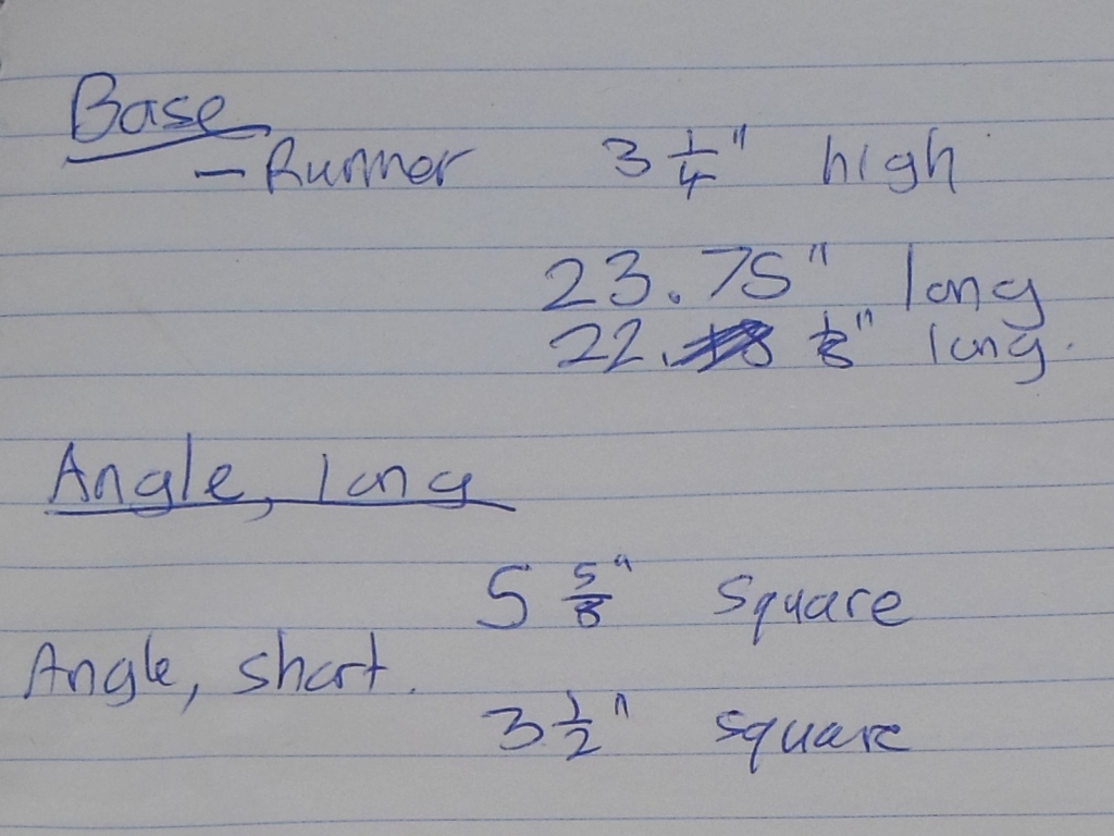
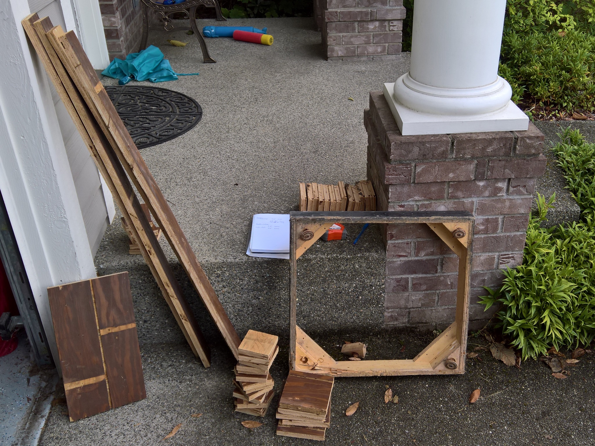
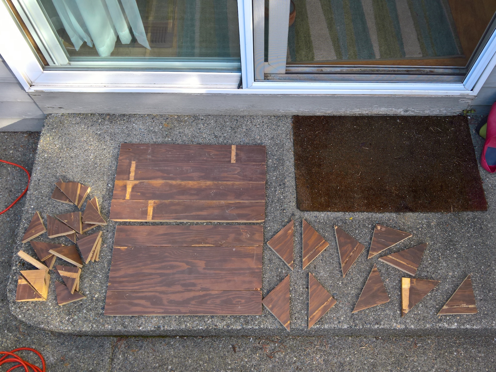
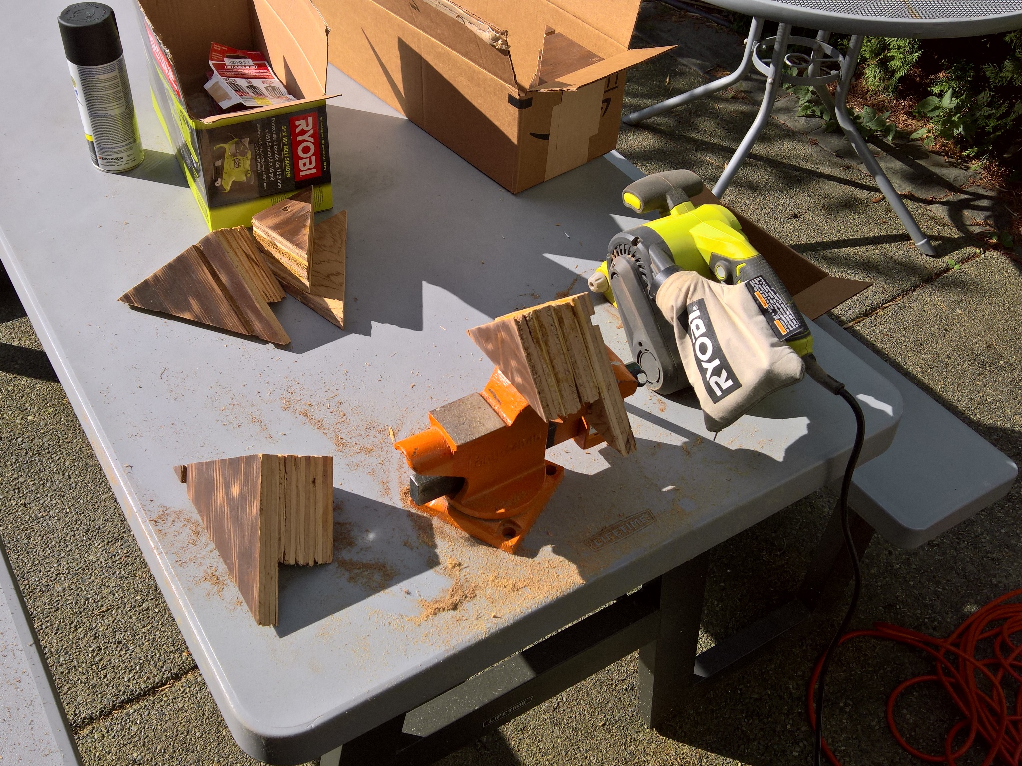
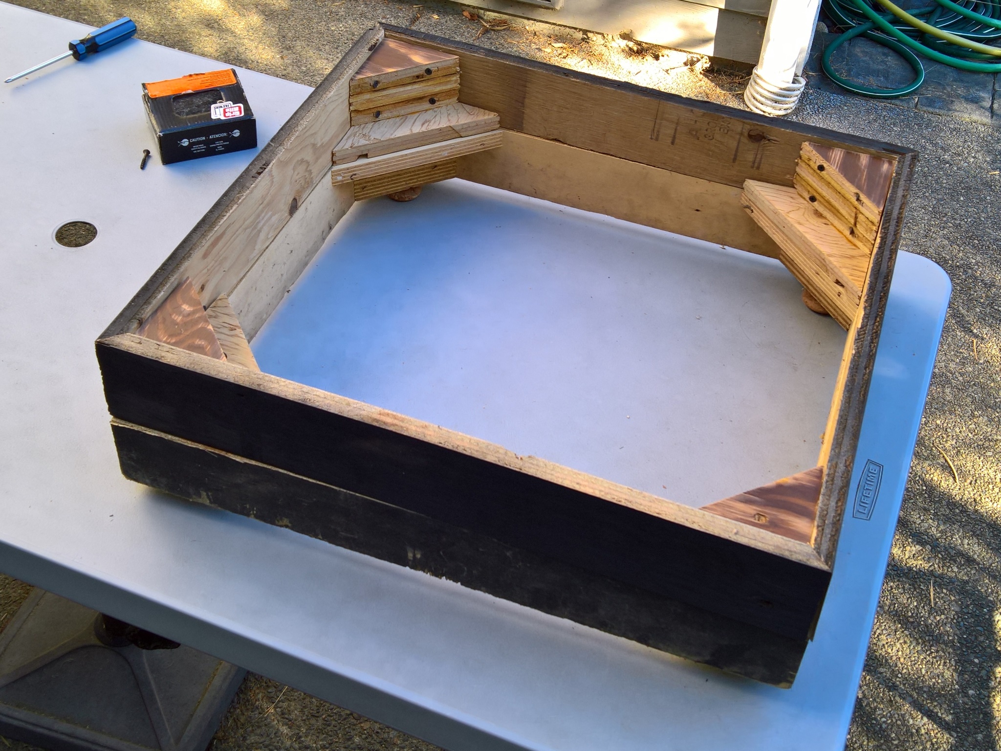
The factory base component parts were 0.75" 5-ply plywood cut as follows:-

|
The table saw was first used to cut the rectangles & squares followed by the angle saw to cut 45 degree edge joins on the skirts and the squares into triangles for the corner brackets.
|
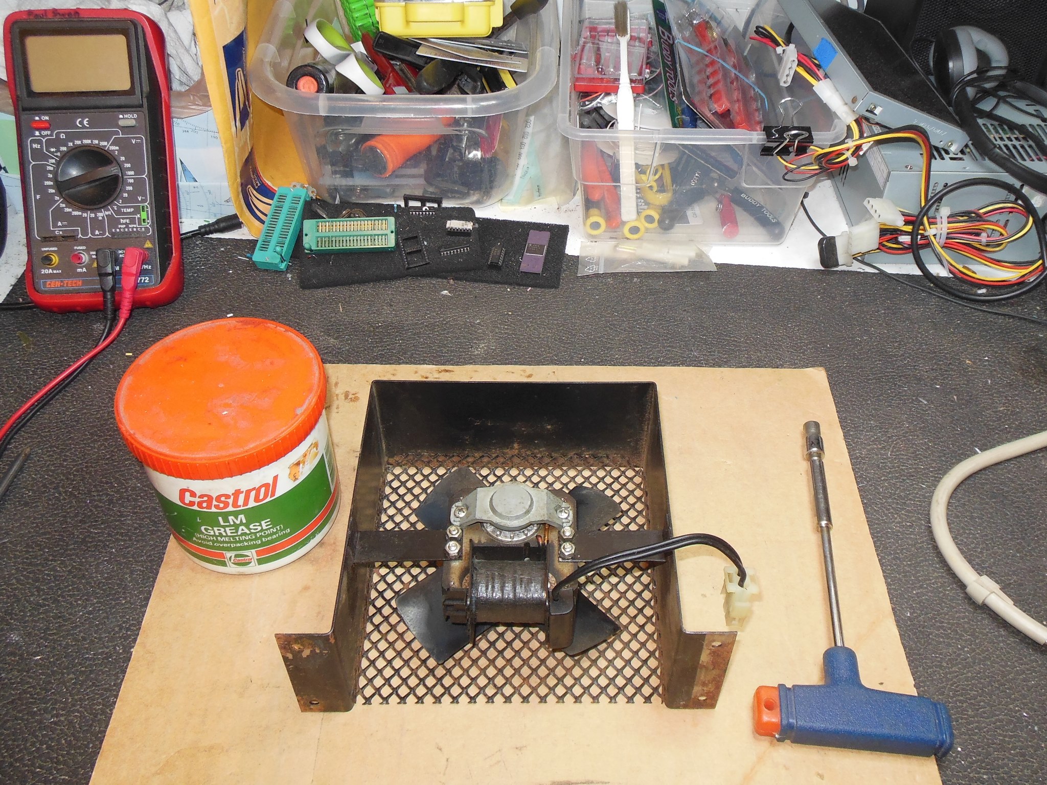
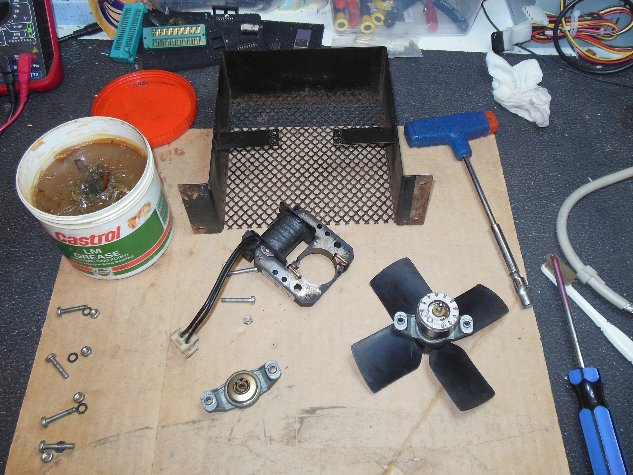
The cabinet fan was disassembled, cleaned & bearings greased.
|
With the horizontal width coil all the way out the picture width was still quite short. With the height adjusted to be full screen the picture aspect ratio looked a bit stretched. I left it as-is for now.
|
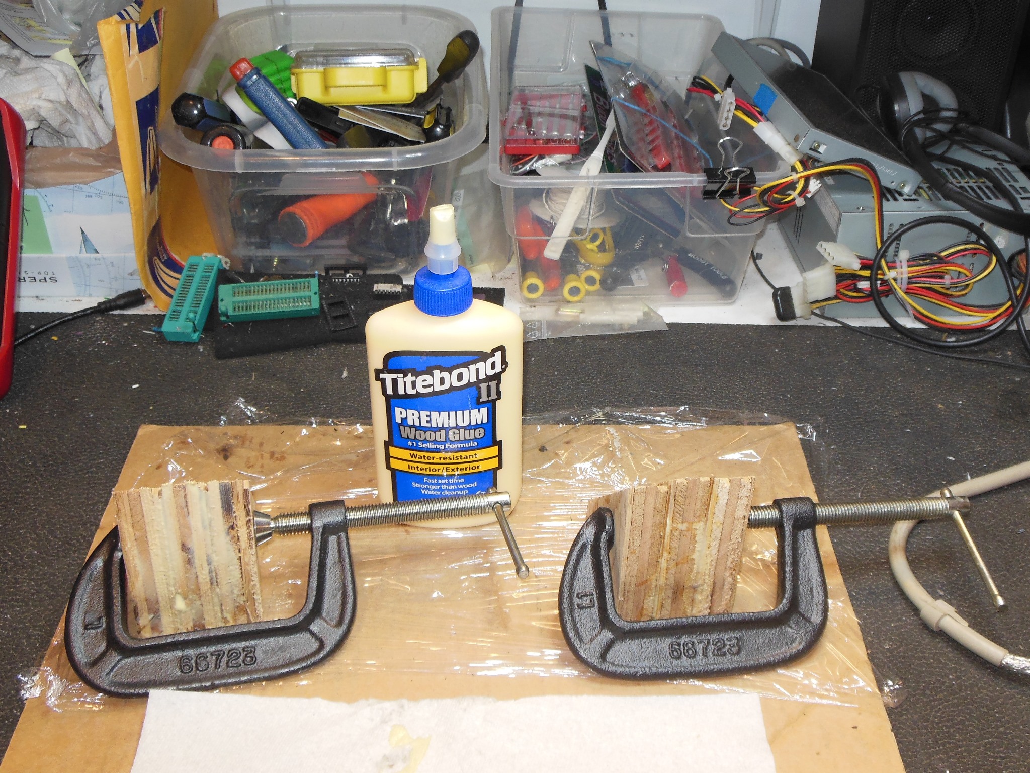
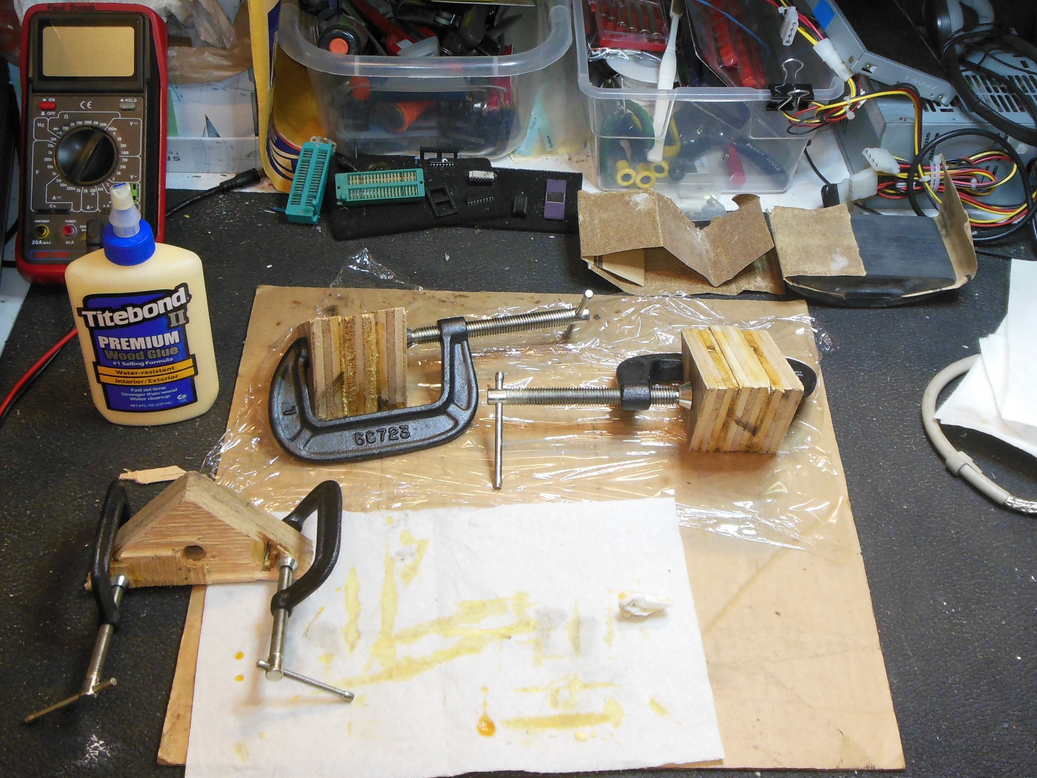
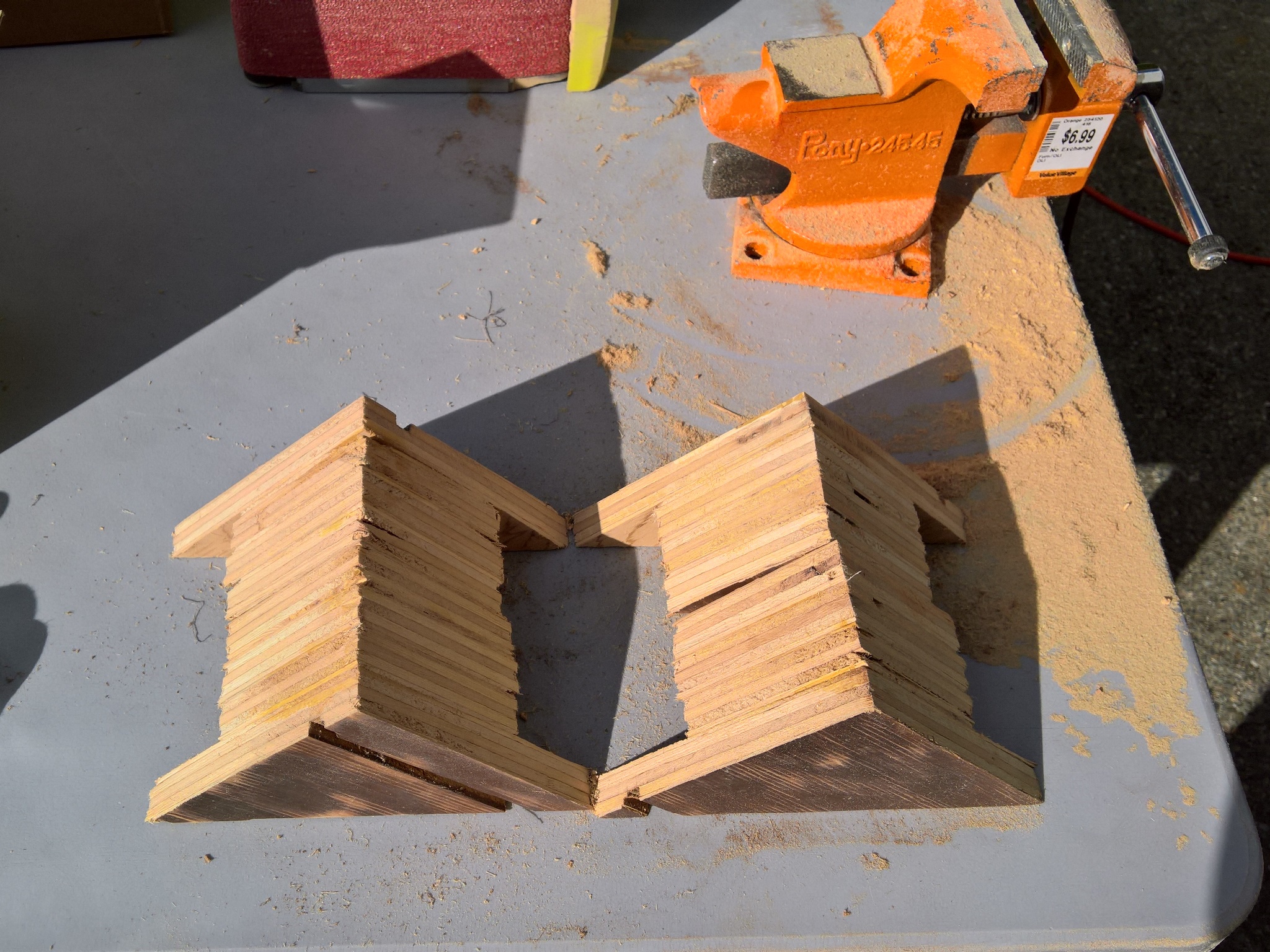
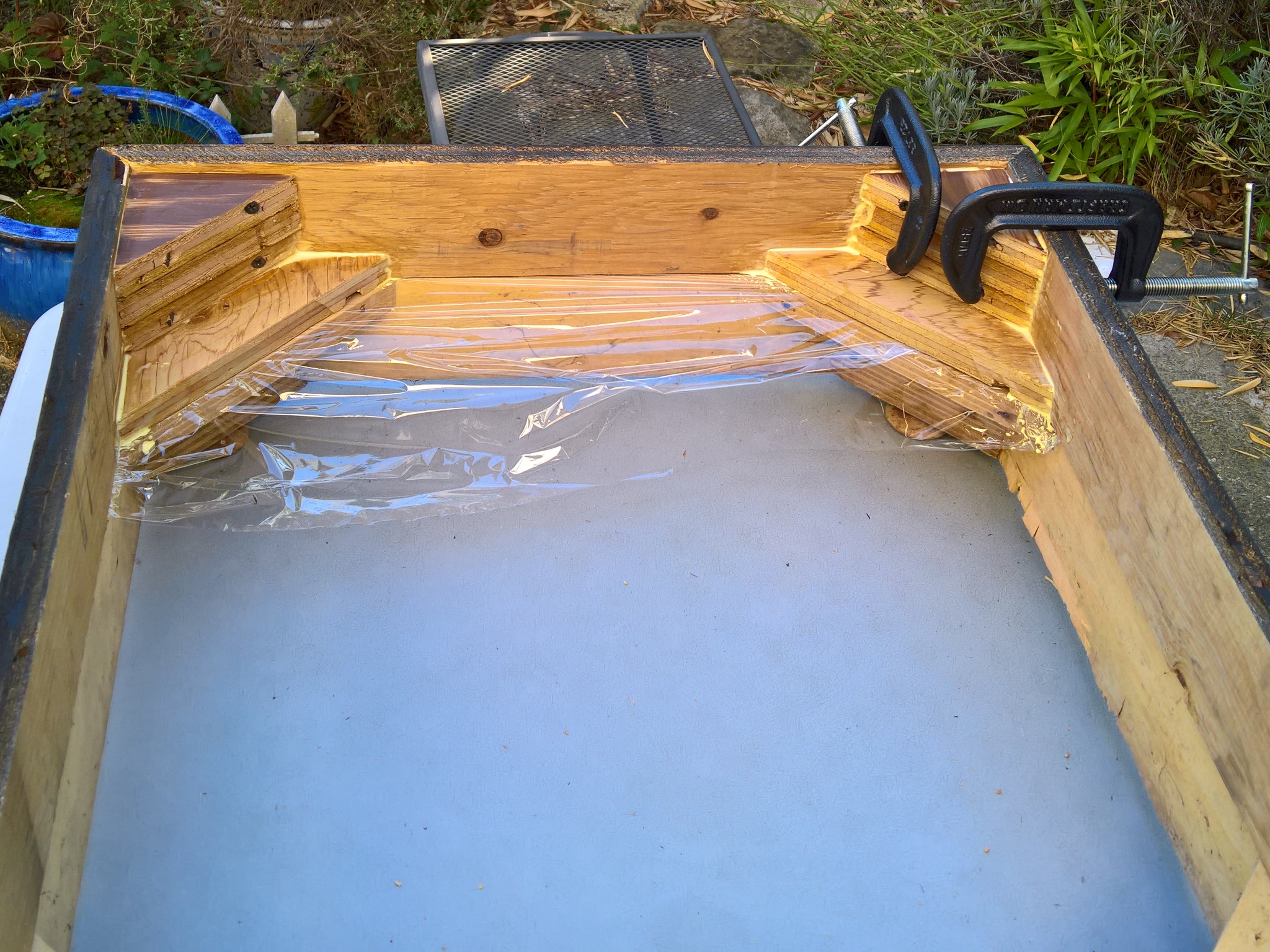
The corner brackets were made up of three small triangles glued together that were set in place with a G-clamp.
|
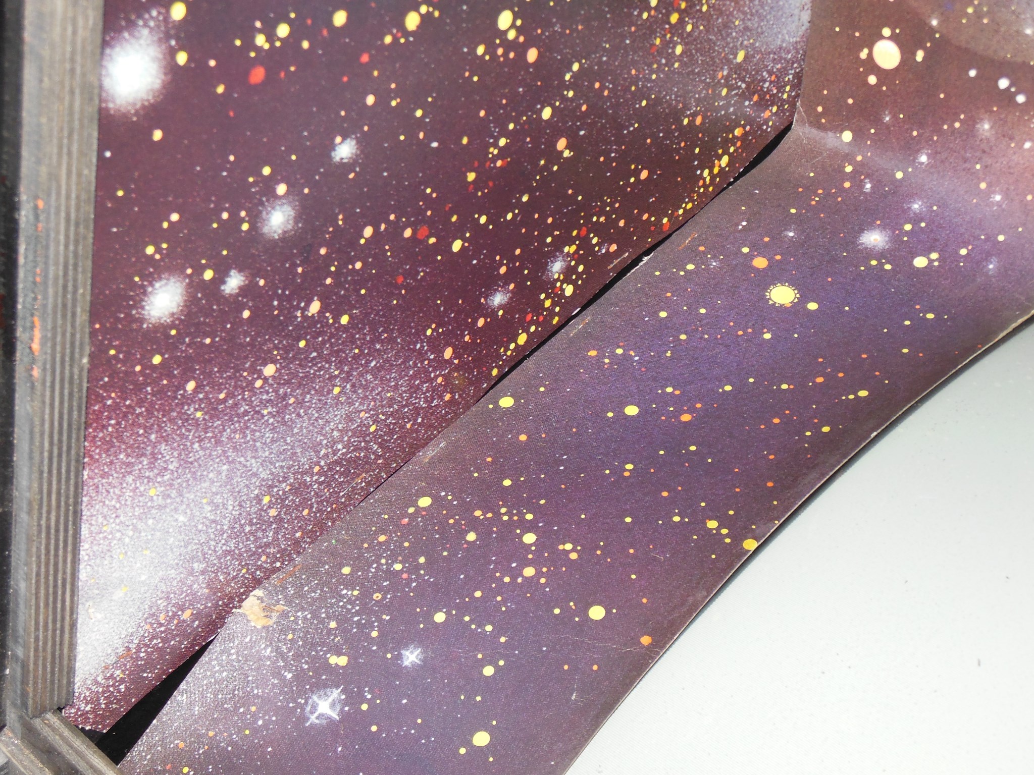
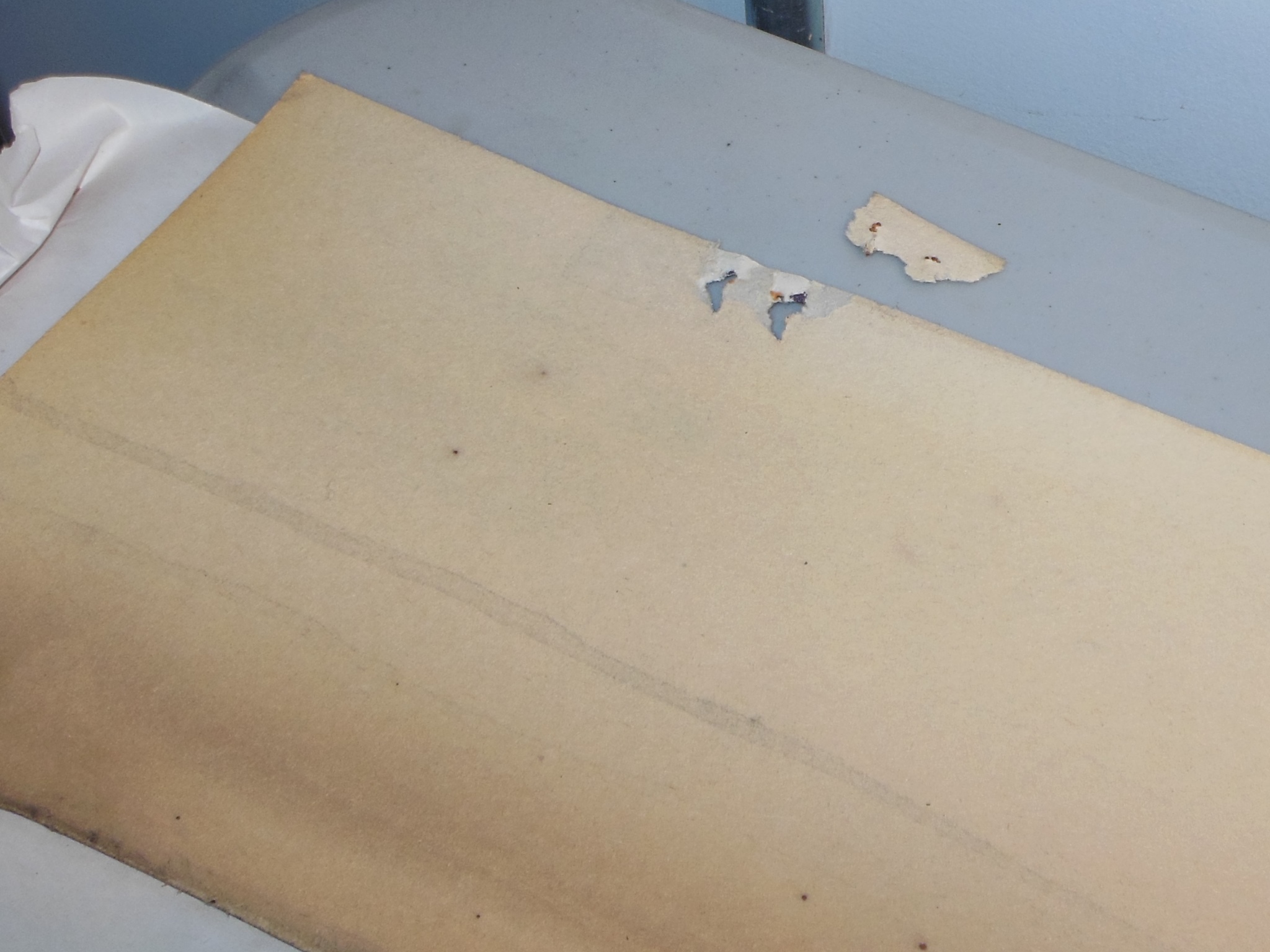
The tears & holes in the bottom portion of the surround were repaired and set.
|
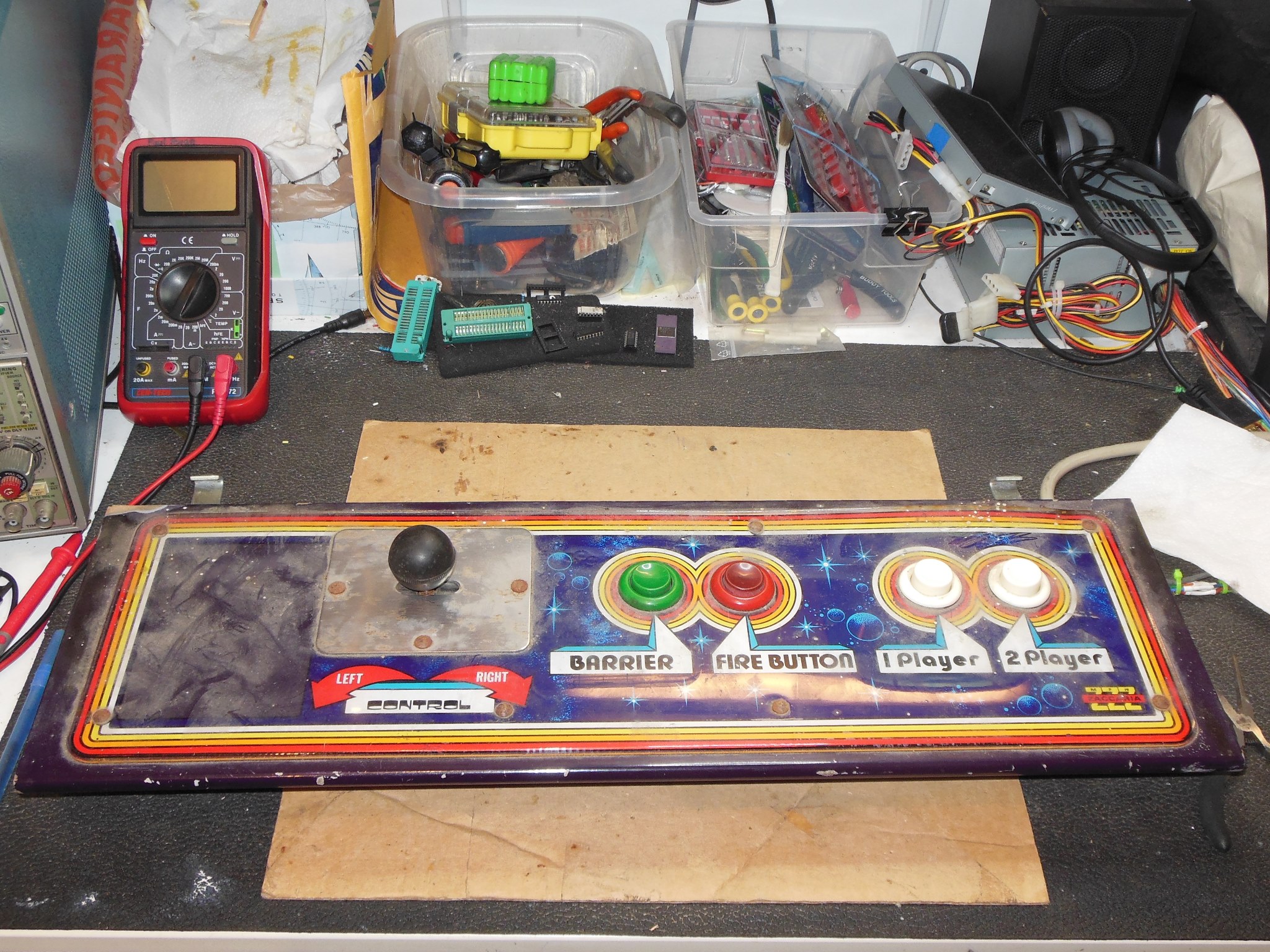
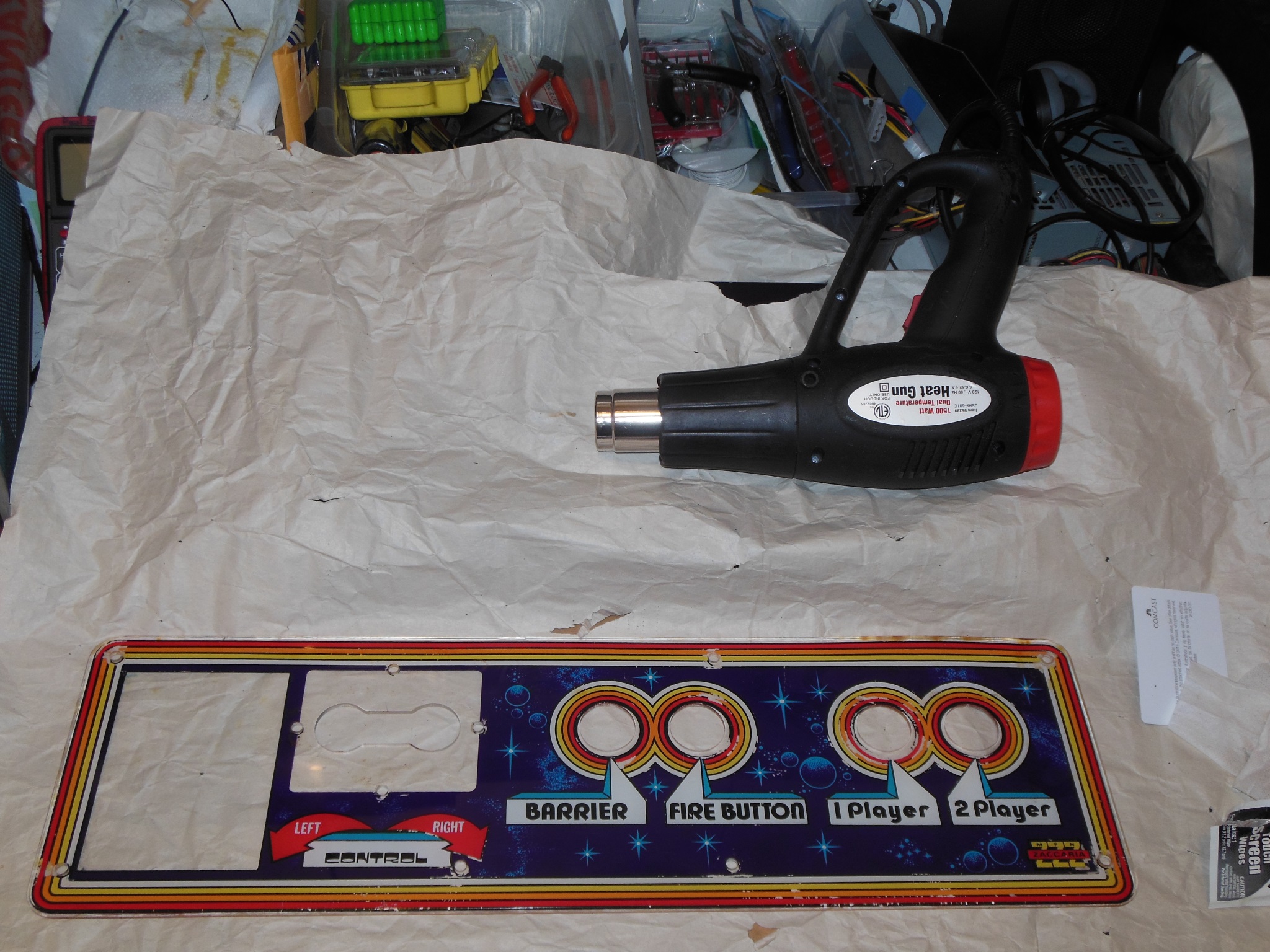
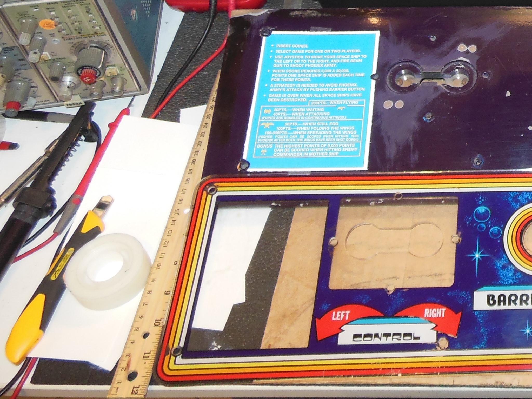
The control panel was complete and in original condition aside from the missing instruction card.

|
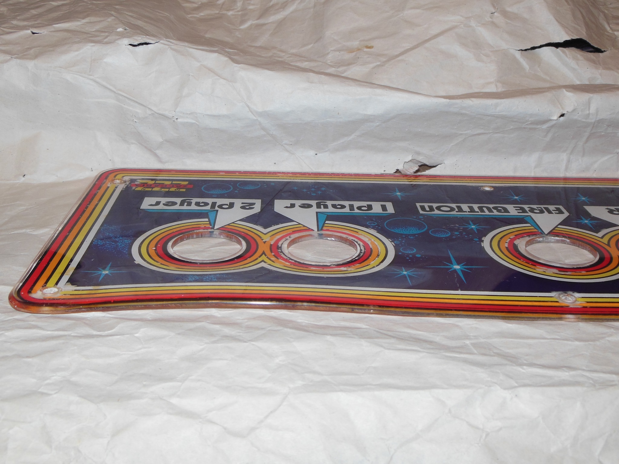
The control panel overlay was worn in places and deformed from cigarette burns along the top.
|
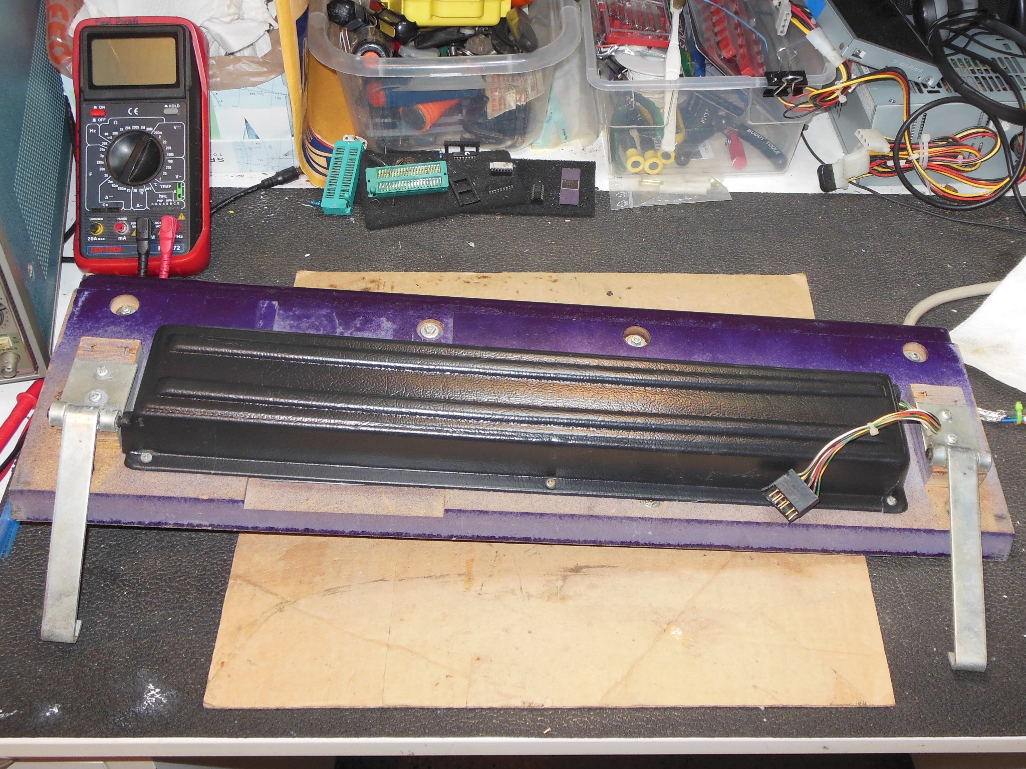
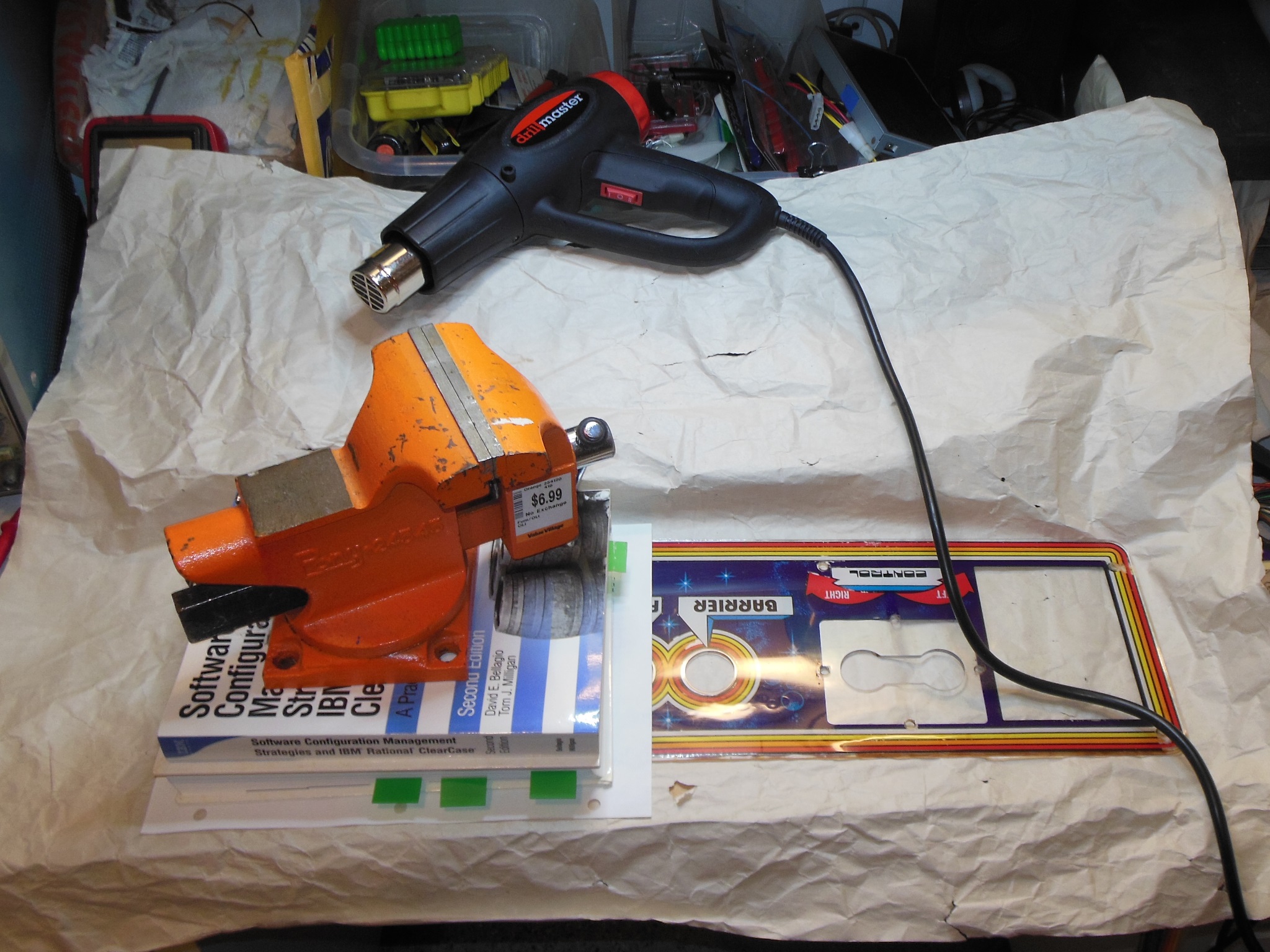
To flatten the control panel a heat gun was used on the low setting to soften the area around the deformity. Once soft, weights were applied to flatten the panel and hold it in place whilst it cooled.
|
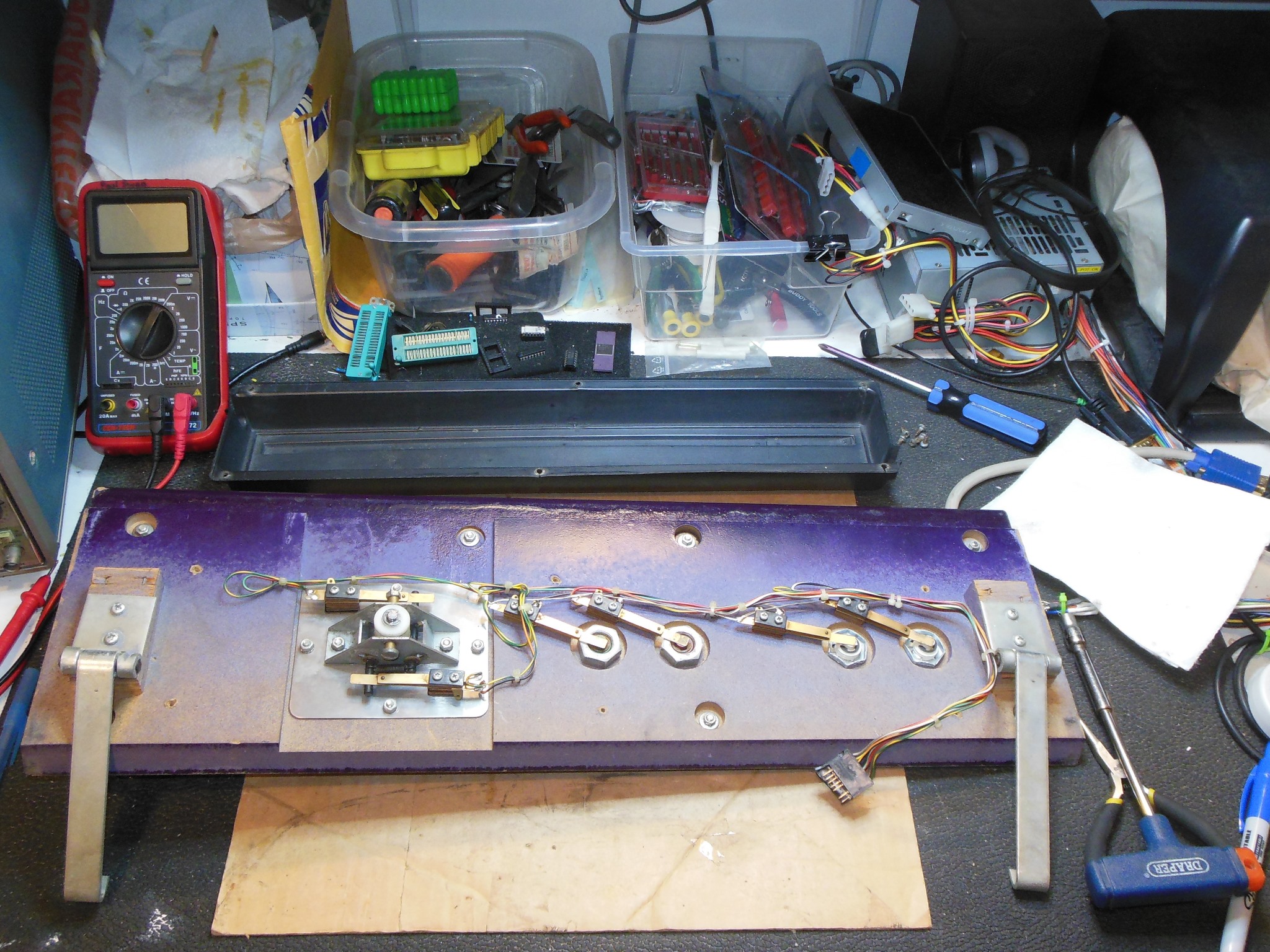
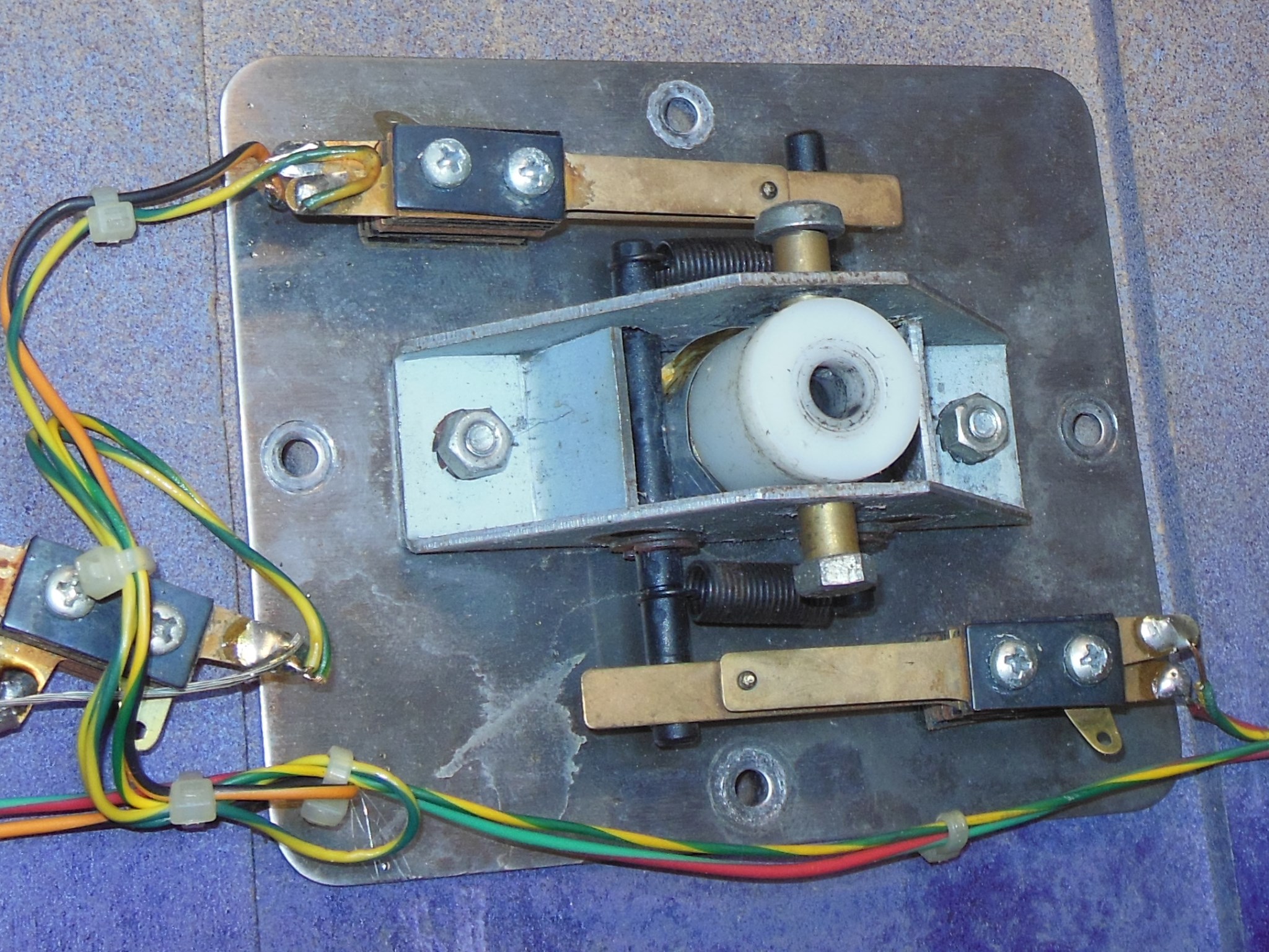
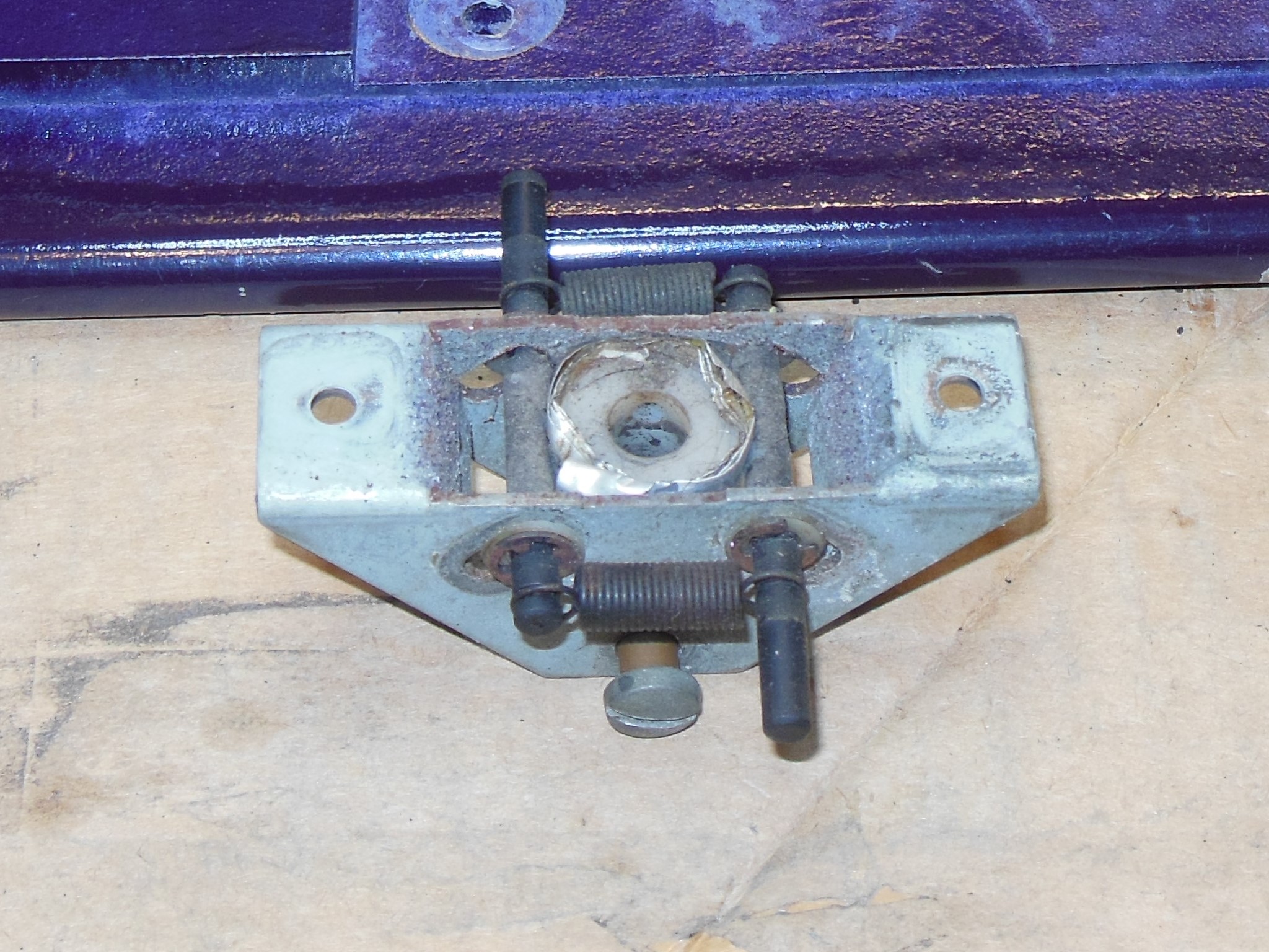
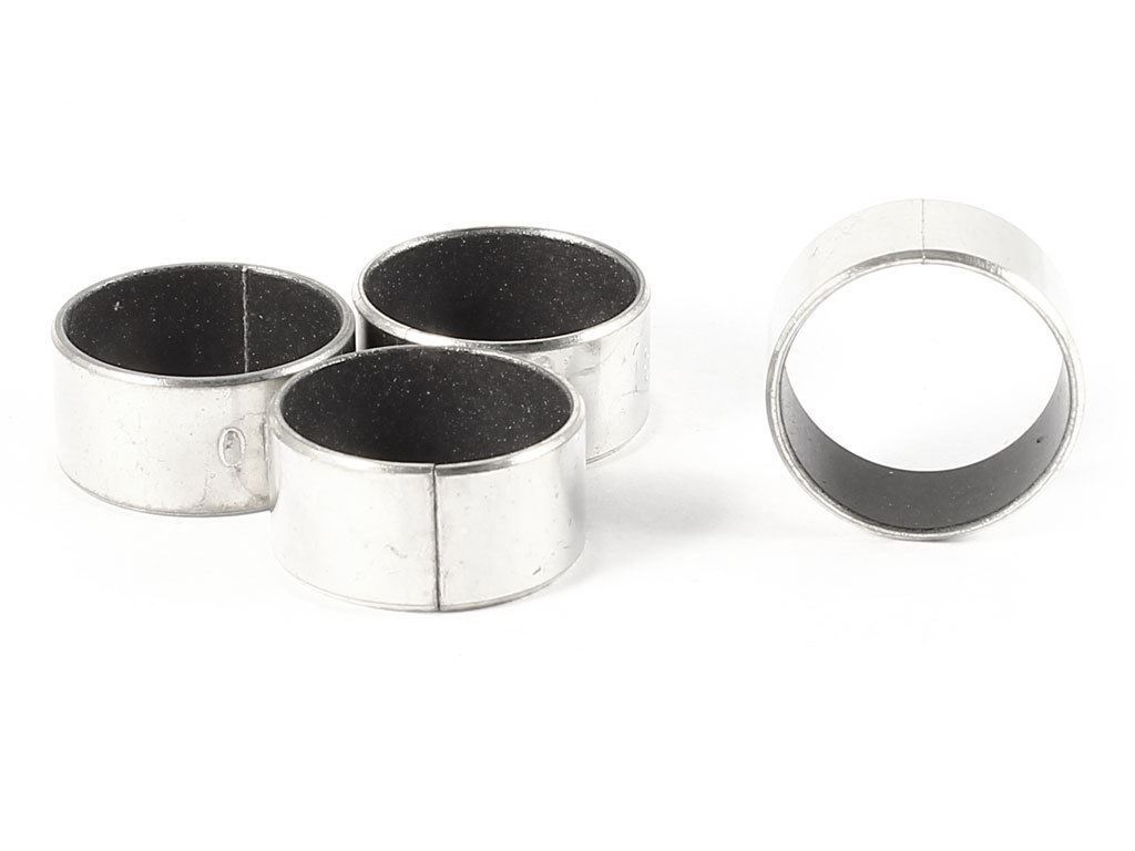
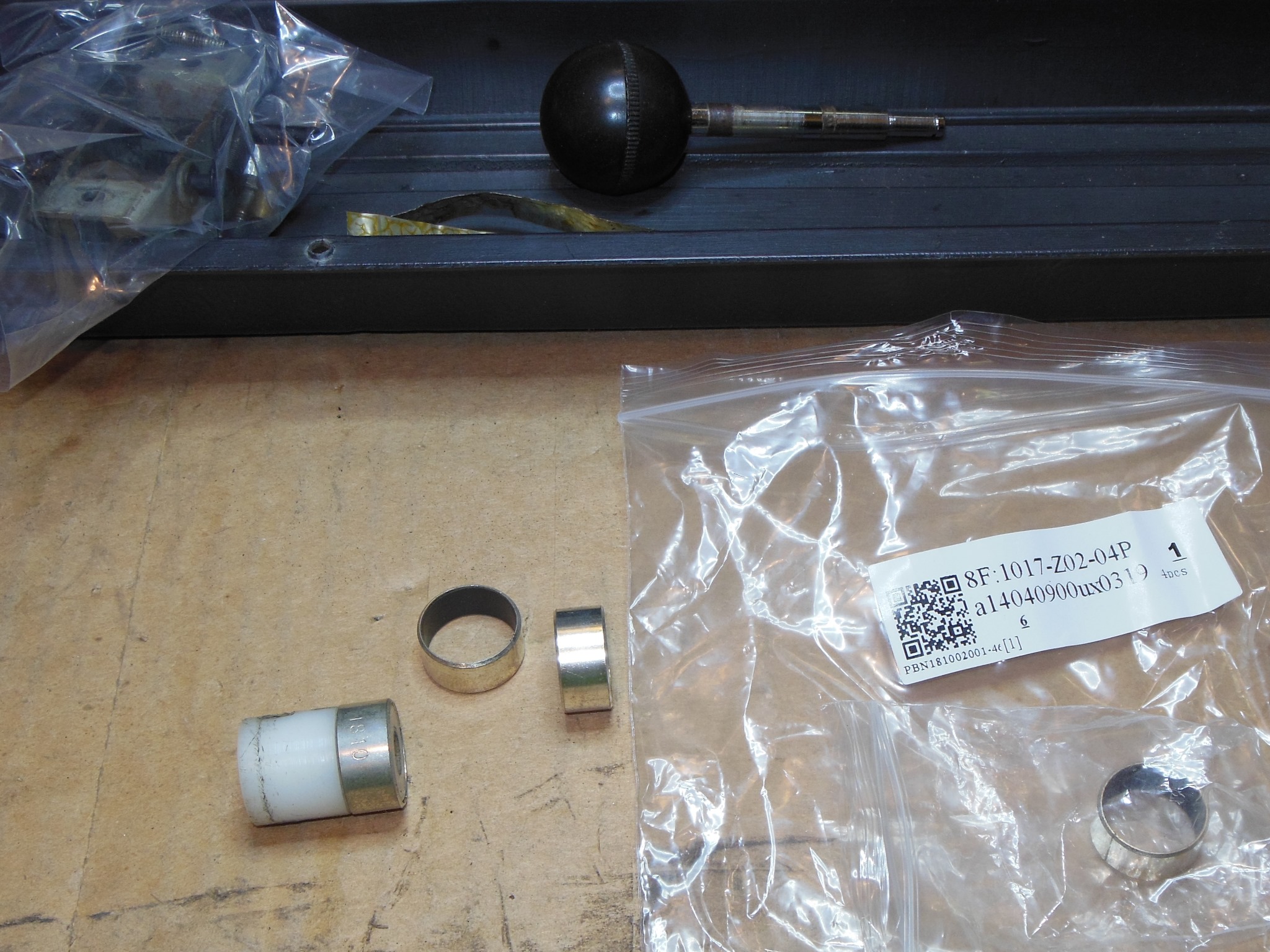
The 2-way joystick wasn't very smooth and appeared to be catching. Inspecting the mechanism found what looked like foil wrapped around the column inside.
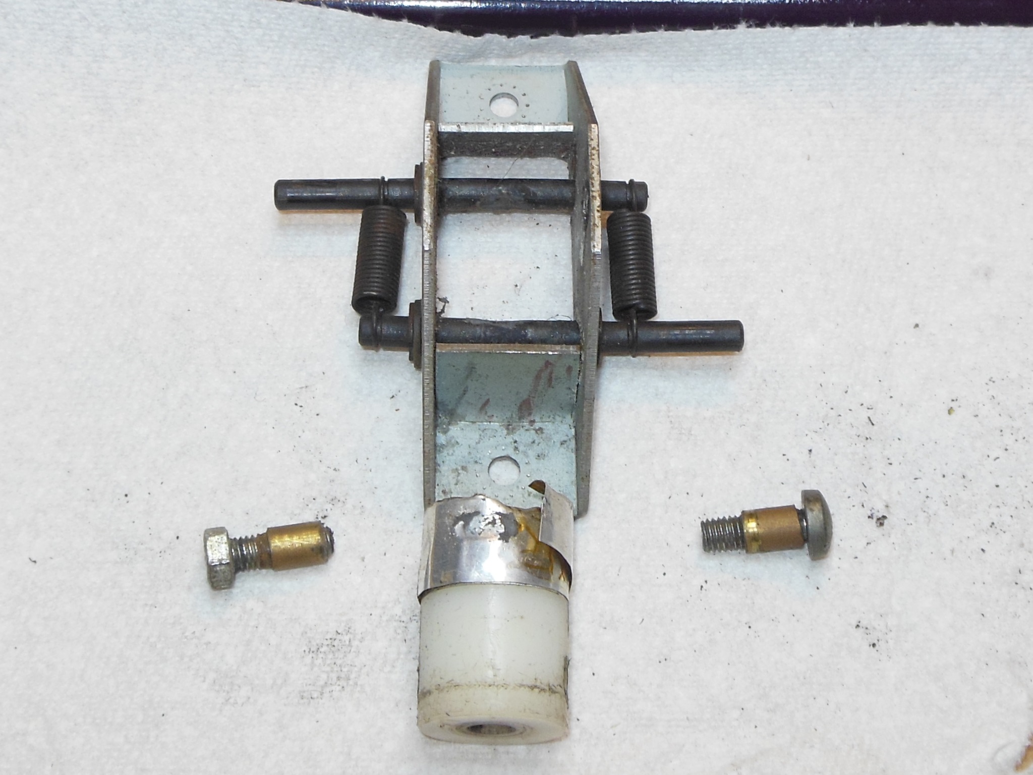
|
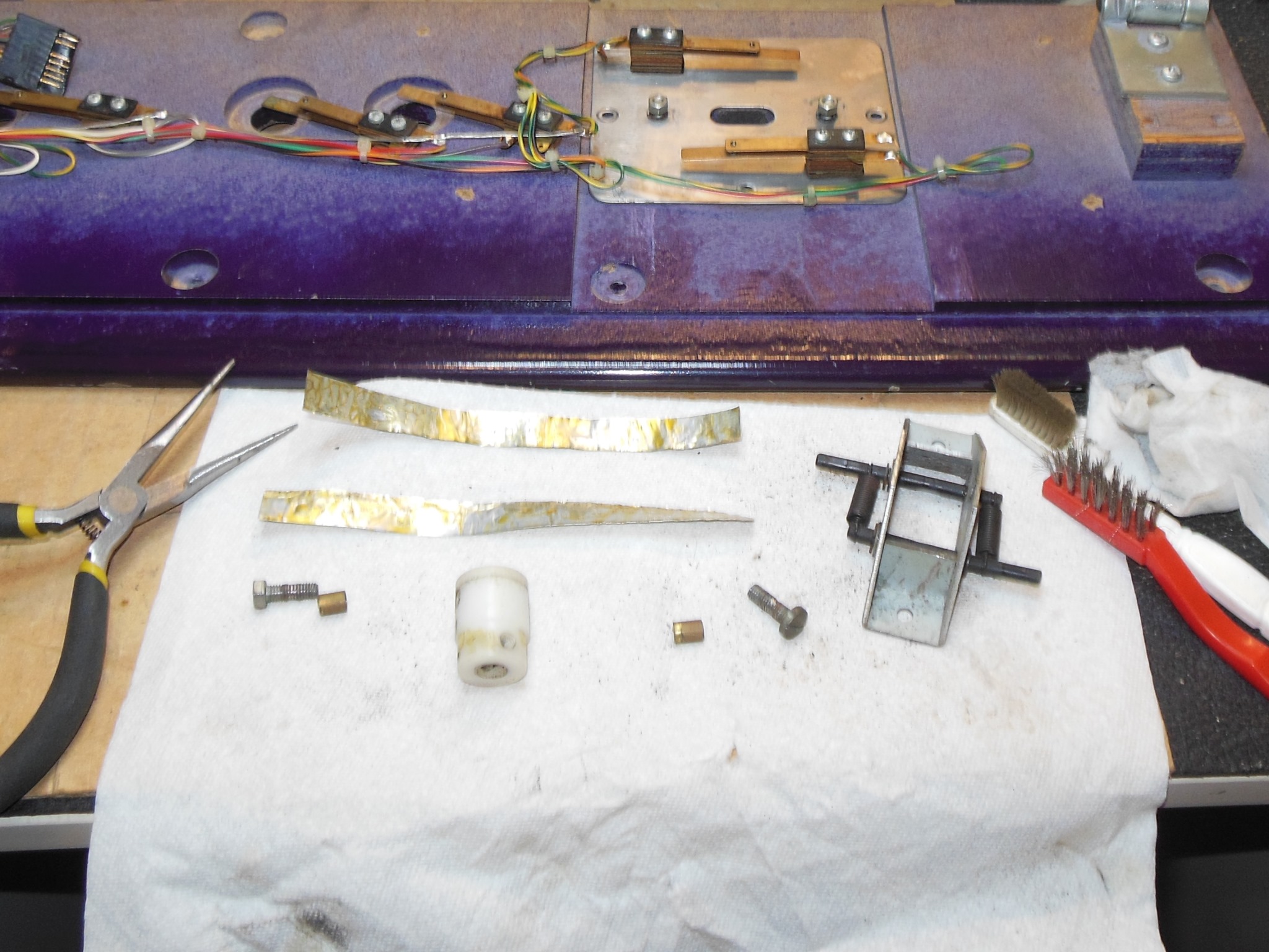
With the joystick completely disassembled I found a couple of layers of single sided foil wrapped around the column. According to the Quasar manual there should have been a metal bearing sleeve attached to the column for contact with the switch rollers. Any replacement sleeve would have to be an exact diameter, exact width and exact thickness to fit onto the end of the column so I was expecting it to be very hard to find a replacement.
|
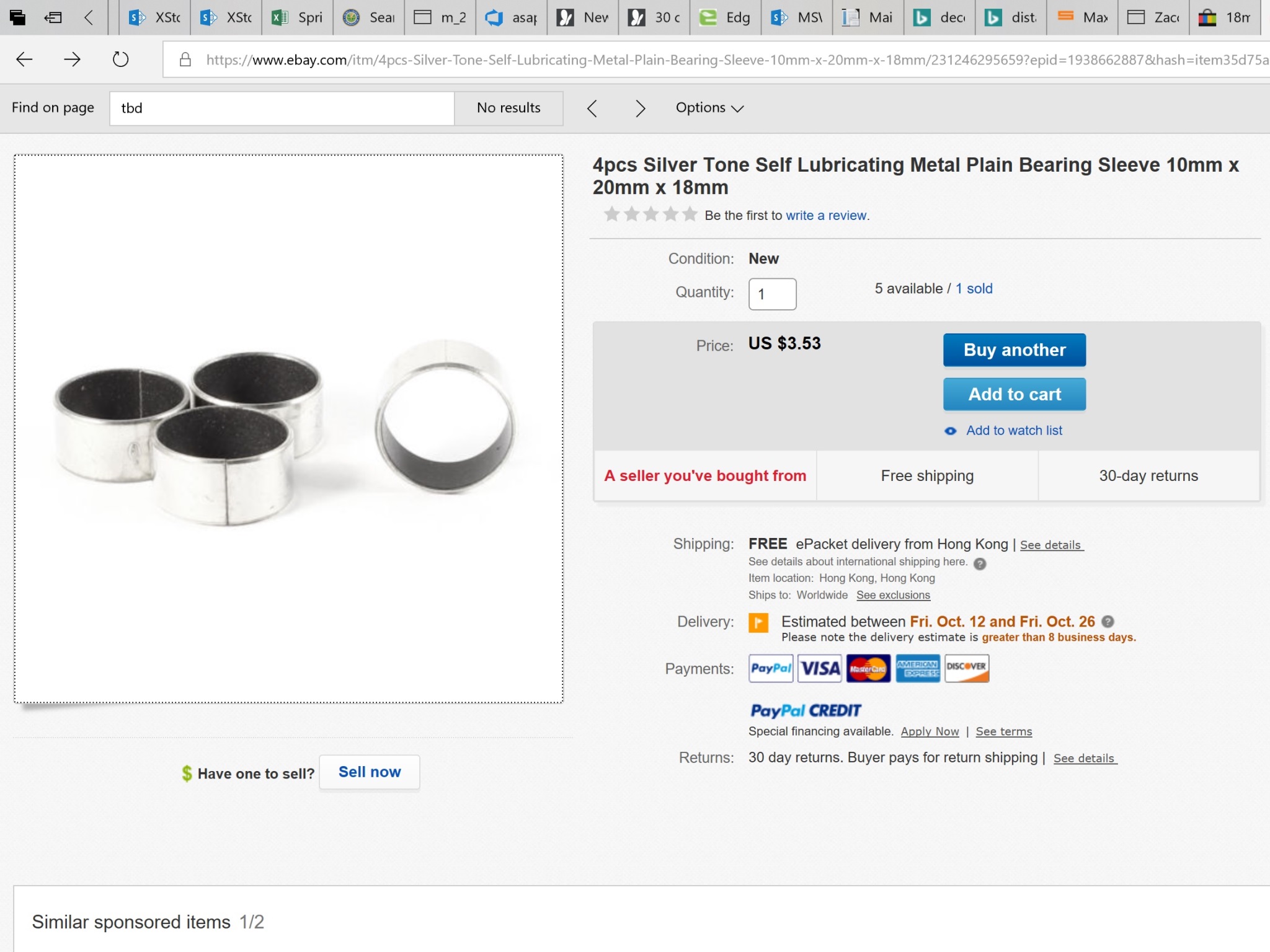
That said, it appeared that eBay had exactly the right replacement that I ordered.
|
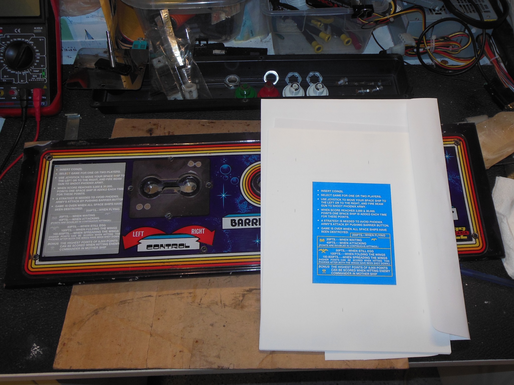
The missing instruction card was reprinted on card using reproduction/restored artwork from the Dragons Lair Fans forum. A paper rough print was used to size & position before trimming down and adding cut-outs To the final colour print. The overlay was then assembled back onto the panel to seal the instruction card in place.
|
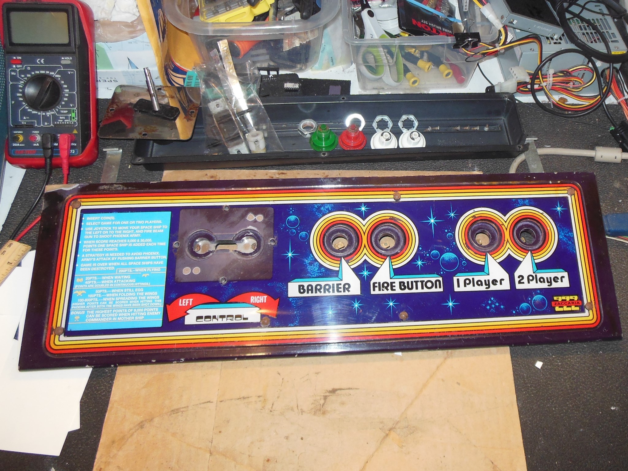
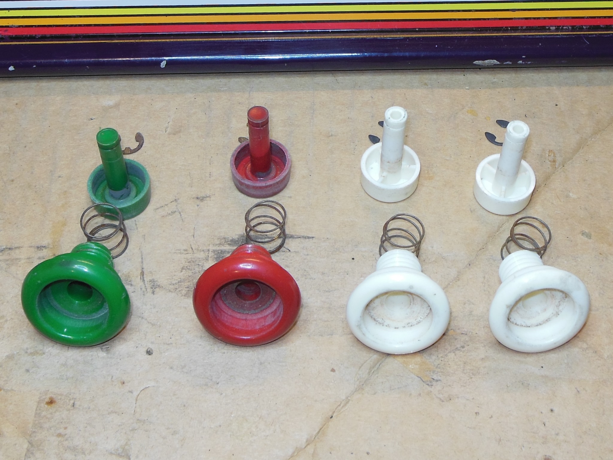
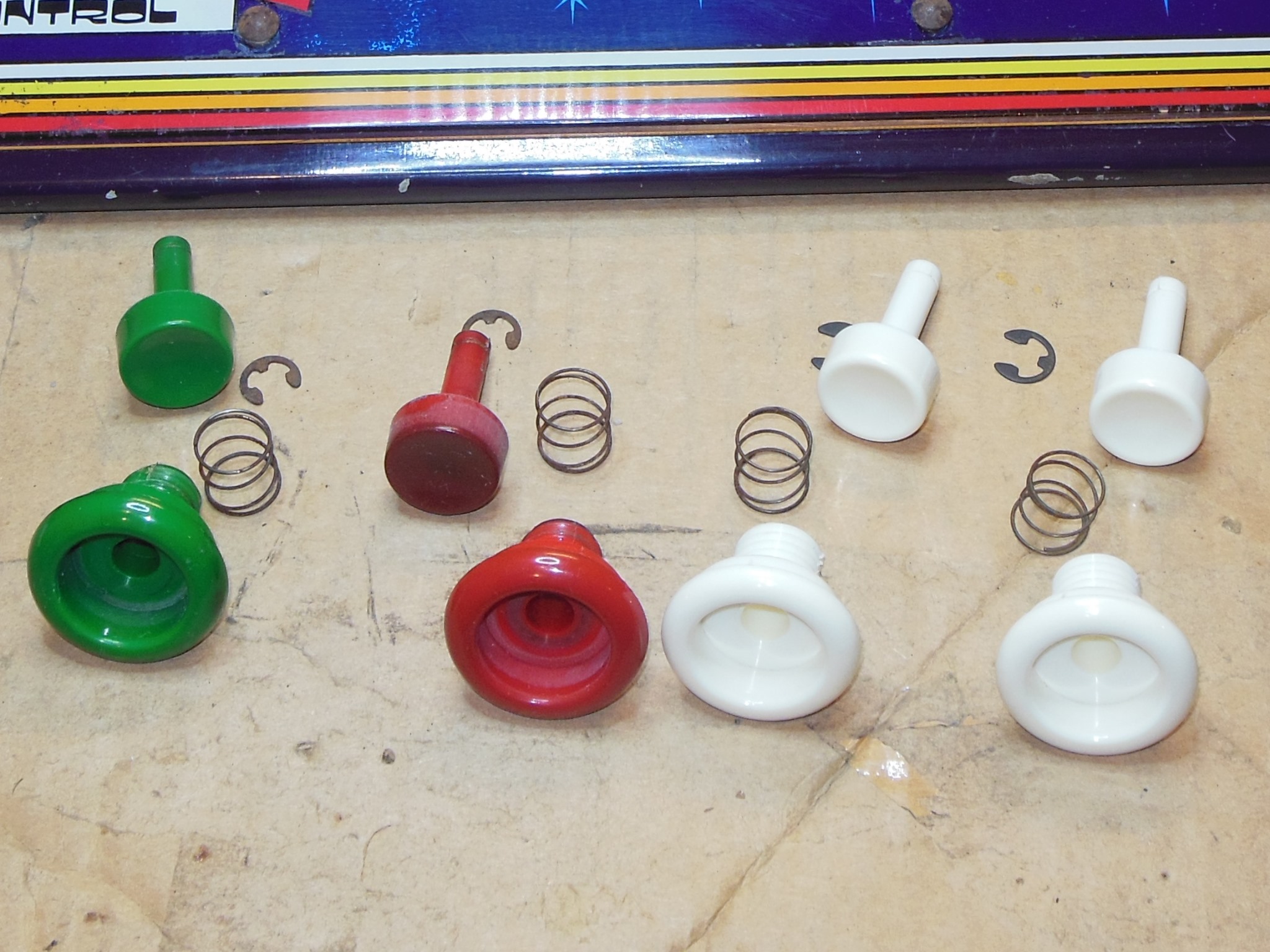
All the buttons were complete and in working condition. A light cleaning was all that was needed.
|
The repairs to the surround had set OK and it was given a final wipe down with a damp cloth.
|
The credit button bracket had been fitted many months ago and I finally completed wiring it into the coin switch.
|
The monitor surround was refitted back into the cabinet using the same method as it was removed on this cabinet, sliding in from the back access hatch.

|
The sleeves for the joystick arrived and they fitted perfectly on the nylon column. The joystick was fitted back onto the panel and the panel fitted back into the cabinet for testing. All the controls were working properly.
|
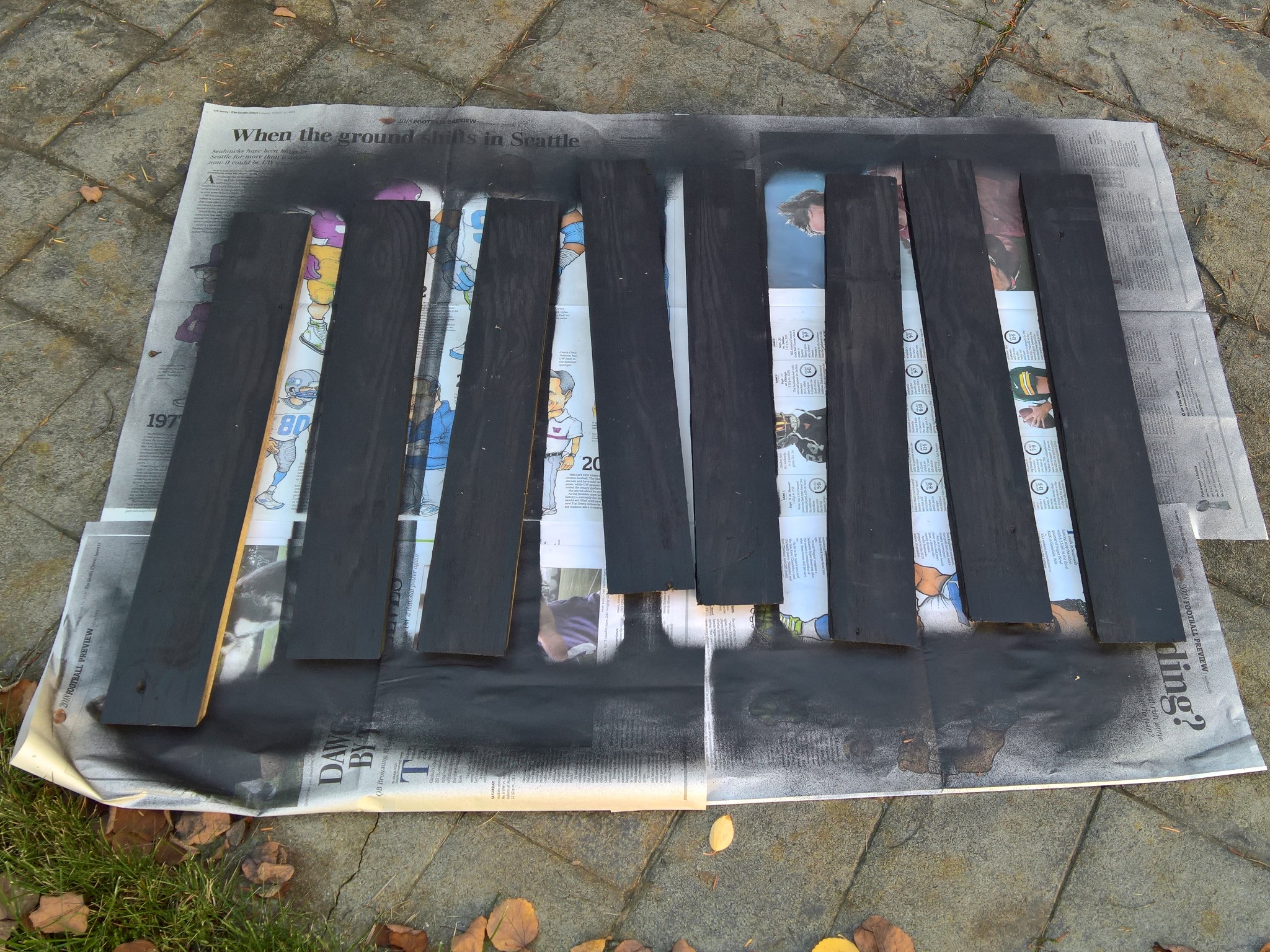
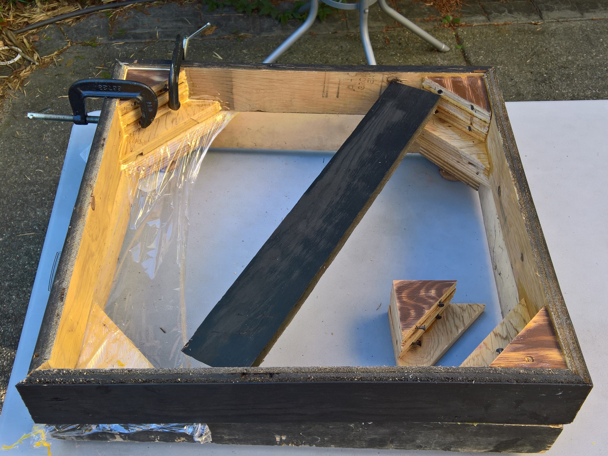
The corner blocks were a little uneven with excess glue that was sanded down smooth. In retrospect, at the factory these were probably assembled into blocks first and then cut diagonally versus cutting and then gluing up into the blocks. The skirts were pre-painted matt black.
|
With the corner blocks & skirts ready to assemble the reproduction base components were staged on top of the factory base to cross check the assembly. Each of the four corners were glued & clamped to the skirts then left to set for 24 hours.
|
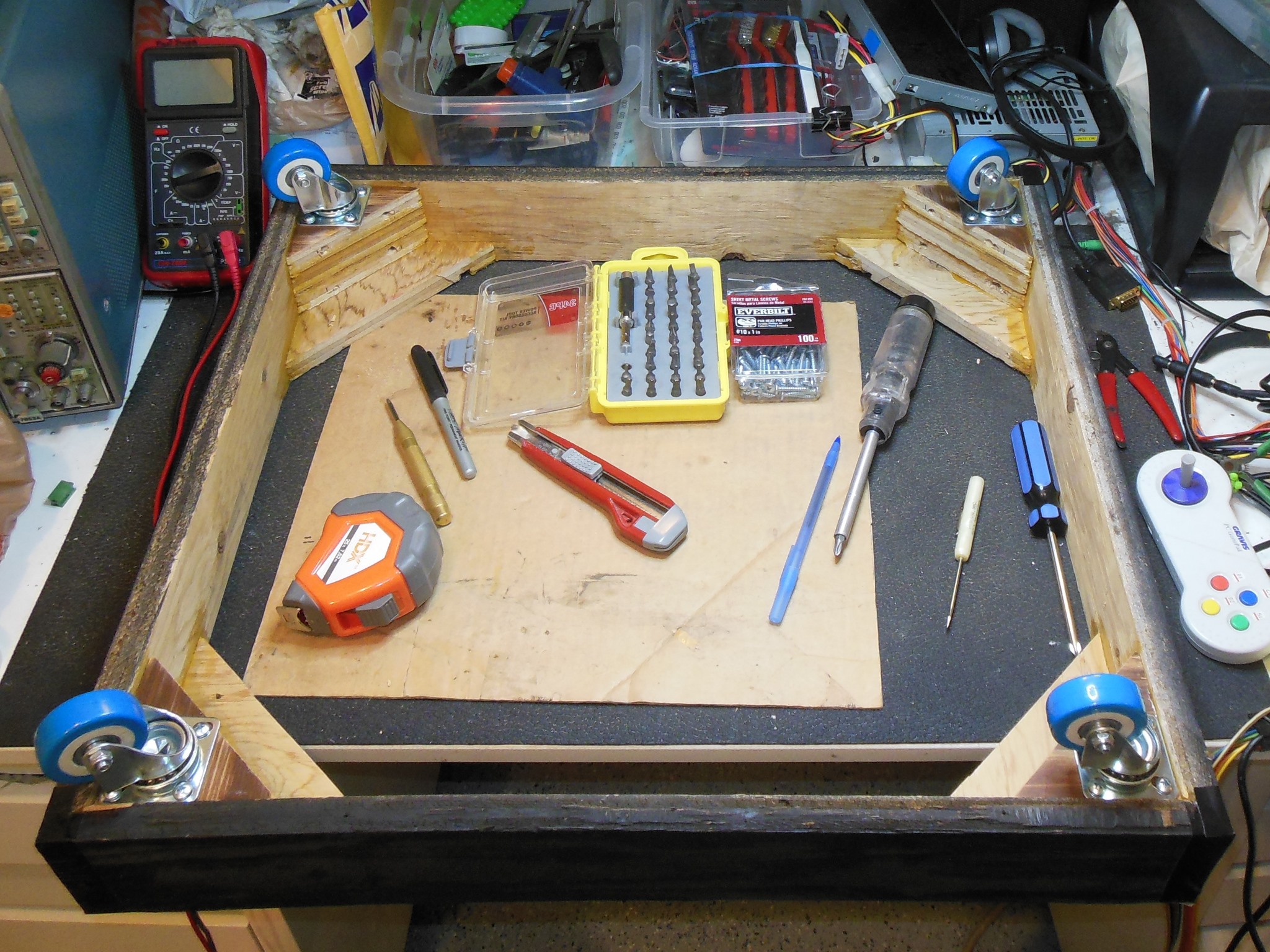
Casters were fitted to the completed base ready for the cabinet. Since the skirt corners did not perfectly meet I used black duct tape as corner end caps to cover the gap. When the base was slotted into the base it was slightly too wide, pushing out the side walls.

|
The sides were sanded down to reduce the width by a quarter inch or so along the overlap with the side walls. Retrying the adjusted base confirmed the fit was good and the sides were spray painted again prior to refitting.
|
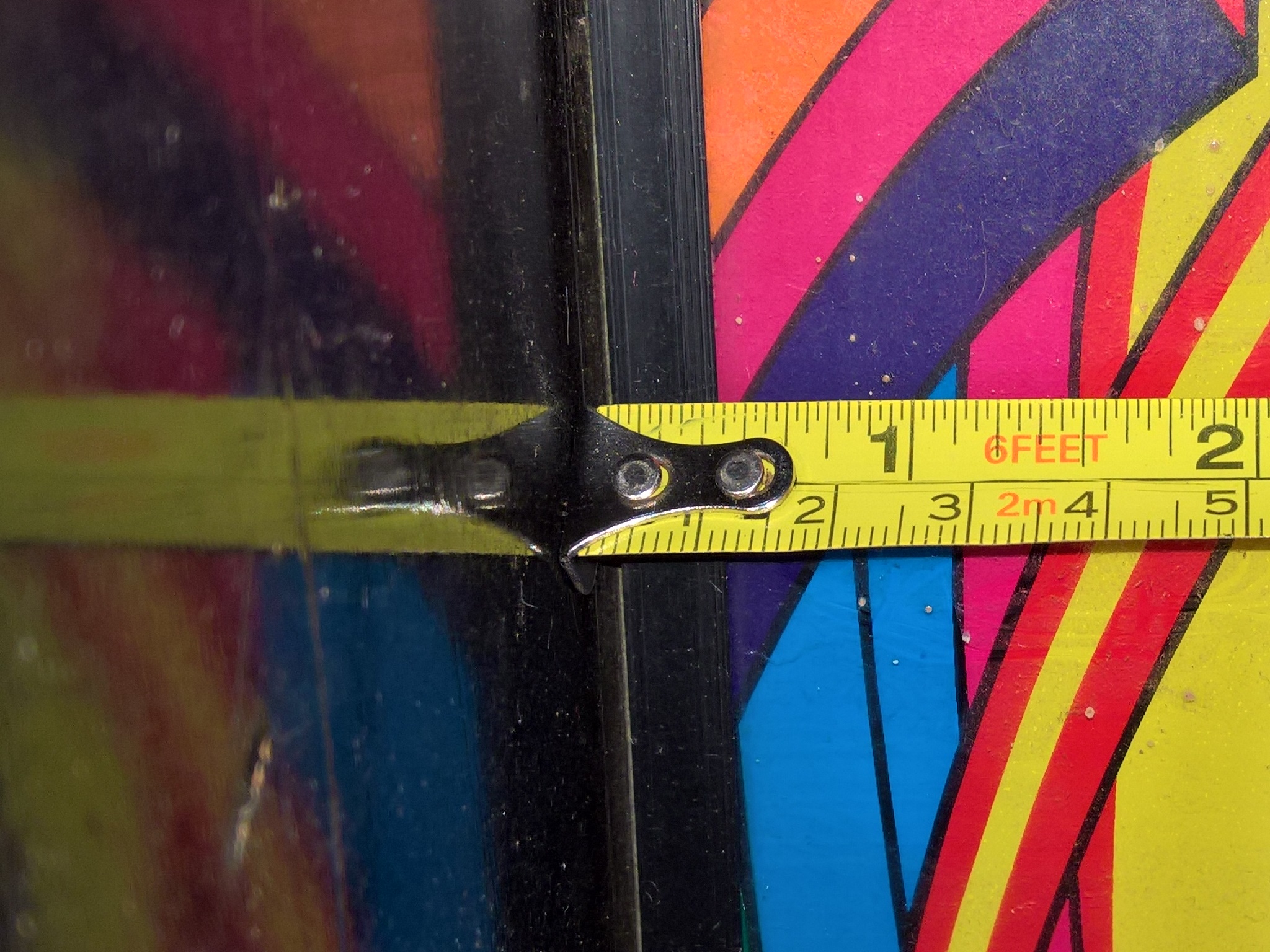
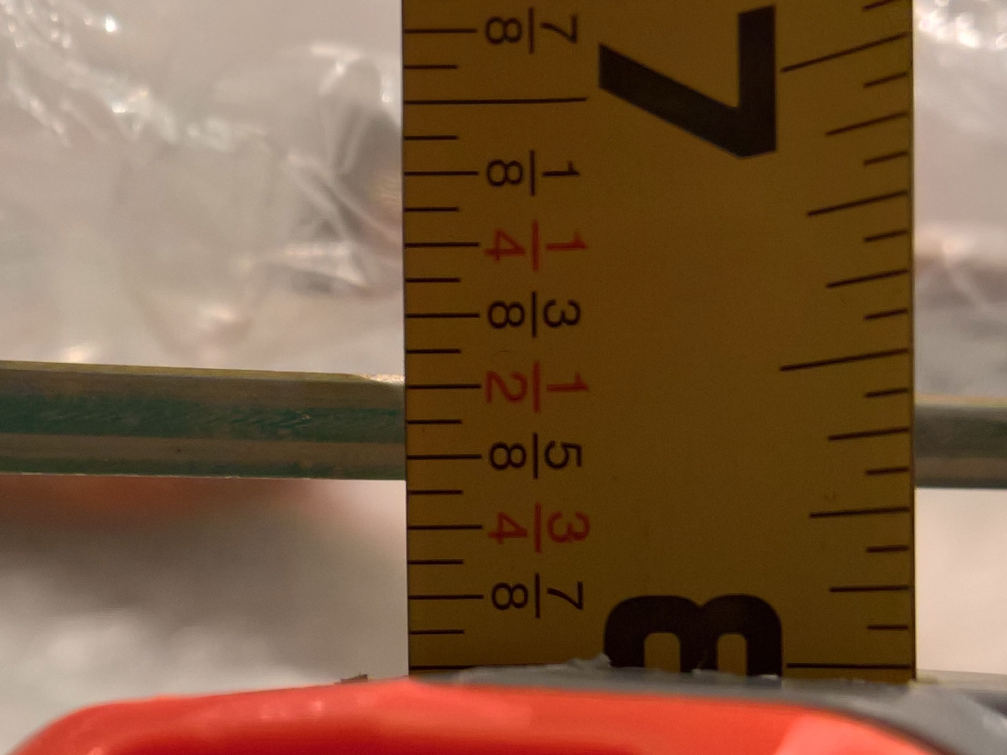
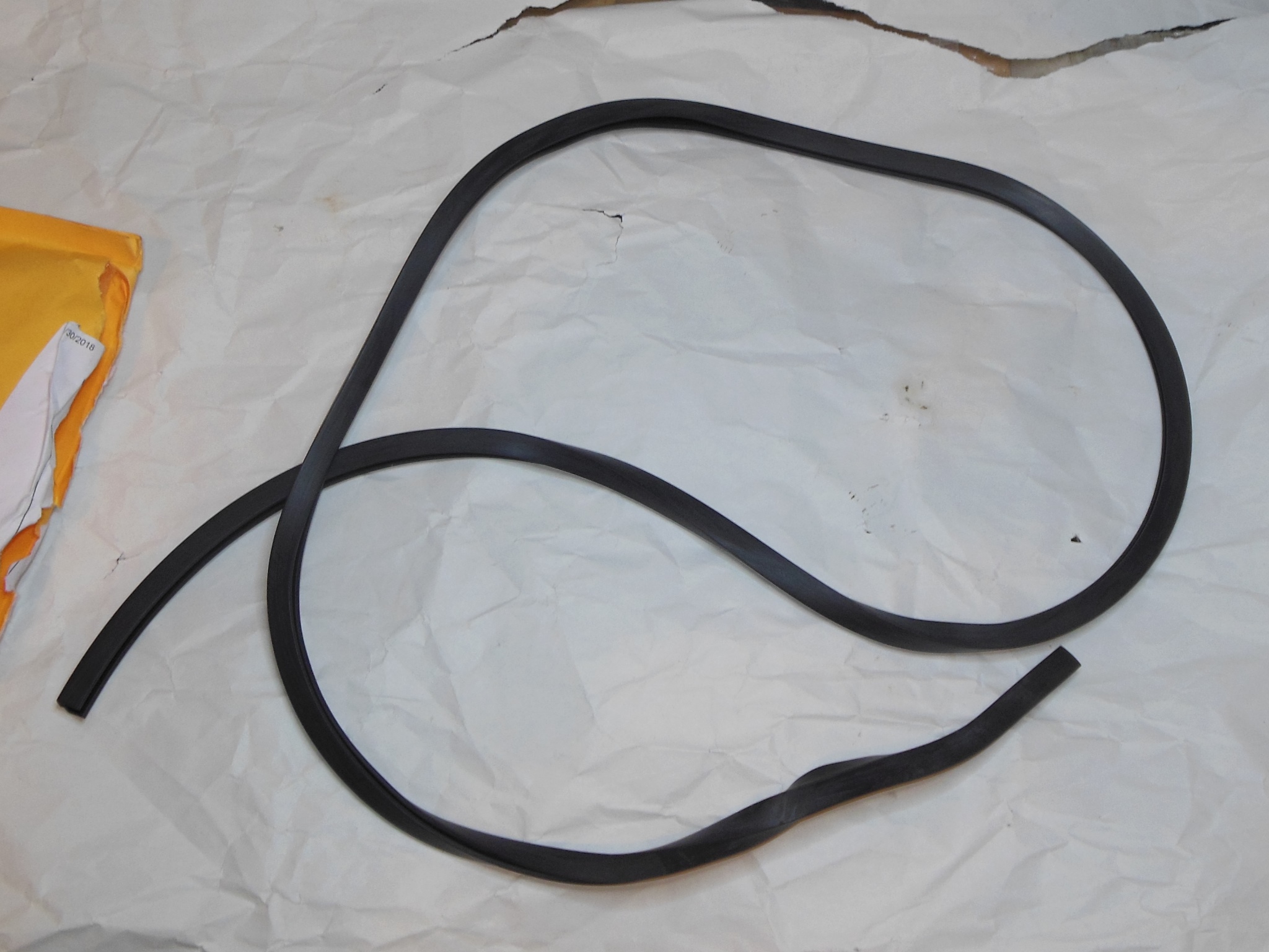
Part of the artwork damage on the monitor glass was cause by the glass resting on the side walls due to the absence of the glass edging. I had no spares left and thus needed to find a replacement for it. The U edging channel measured approximately 5/8" wide by 3/8" thick.


|
The closest I could find on eBay was 8mm x 8.5mm for 4mm to 5mm glass. I ordered a length to try out.


|
The U edging for the monitor glass arrived. The fit on the glass looked good and it was cut down to height. This soft rubber edging was thicker than the original hard plastic but still looked OK. However, on attempting to fit the monitor glass back into the cabinet I discovered that the thicker edging made the glass too wide to fit into the cabinet :(

|
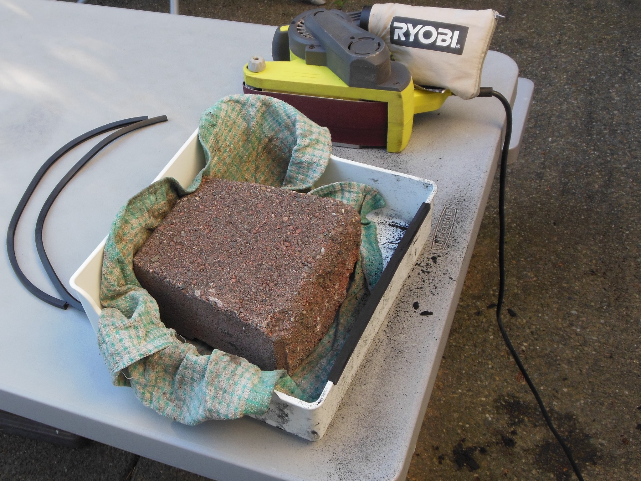
To fix the edging the plan was to mount it on a plastic box and use a belt sander to reduce its thickness. I tested out a small section of left over edging first to confirm if this would work and the edging still had enough grip on the glass. It looked like it would work and I went on to sand down the two glass strips (generating a mess of black rubber dust in the process). With the trimmed edging refitted the glass did now properly fit into the monitor cavity :)
|
With a smaller reproduction PCB mounting plate (0.063" x 14.0" x 11.5") from OnlineMetals.com drilled with PCB & cabinet mounting holes the PCB plate assembly was Built & mounted into the cabinet.

|
|
|
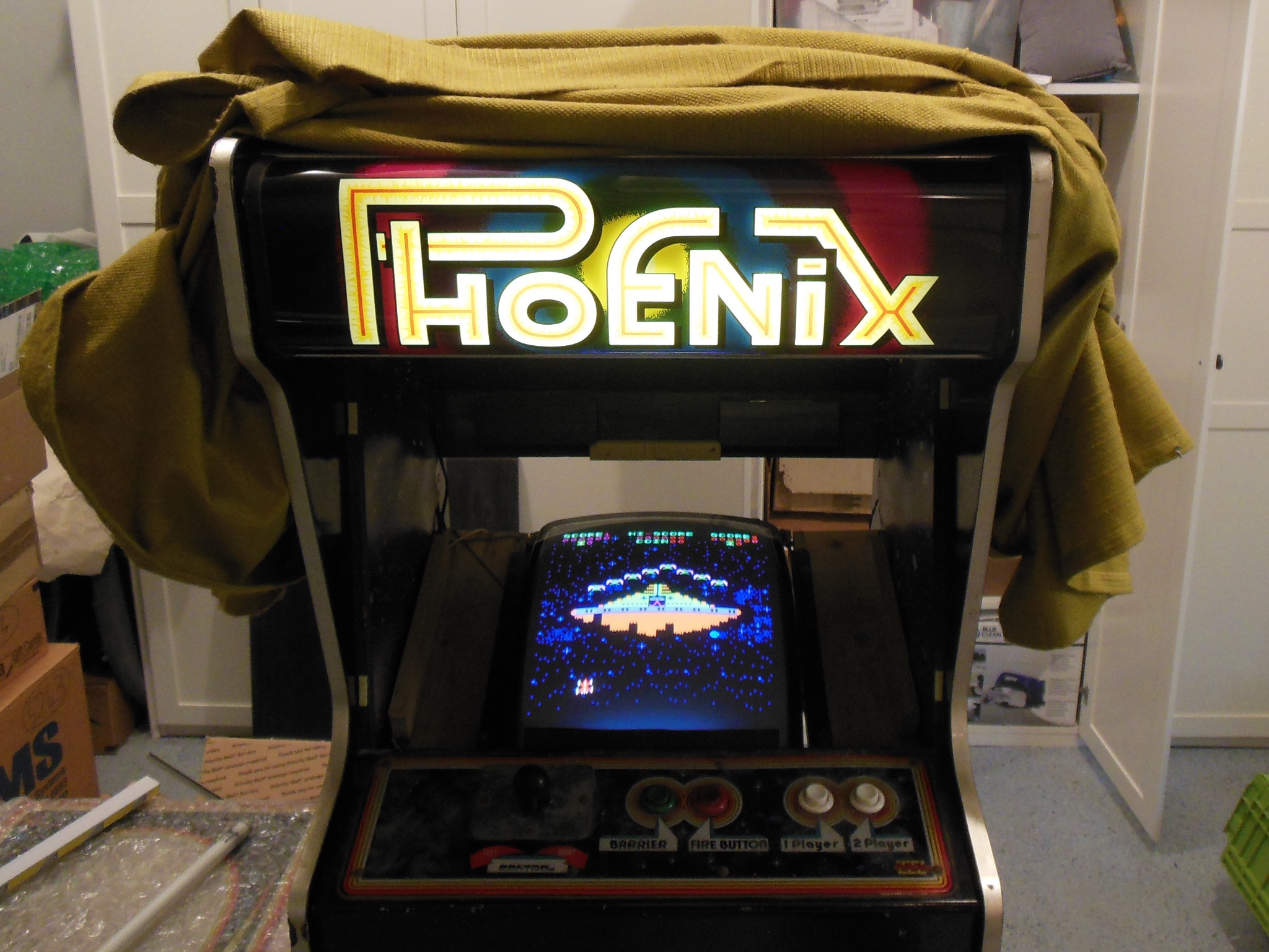
The game restoration was complete and burn-in testing started.
|
During burn-in testing the barrier button stopped working. Checking the control panel found no issue with the button itself so I clipped in a multimeter to the barrier input on IC 12 pin 14 (74LS157). The button input to the IC had good logic high (4.5V) and low (0V) when the button was pressed so I suspected the IC 12 was bad. With the game PCB on the bench, the barrier button was still not working confirming a PCB problem. Replacing IC 12 (74LS157) fixed the barrier button input and burn-in testing resumed.
|
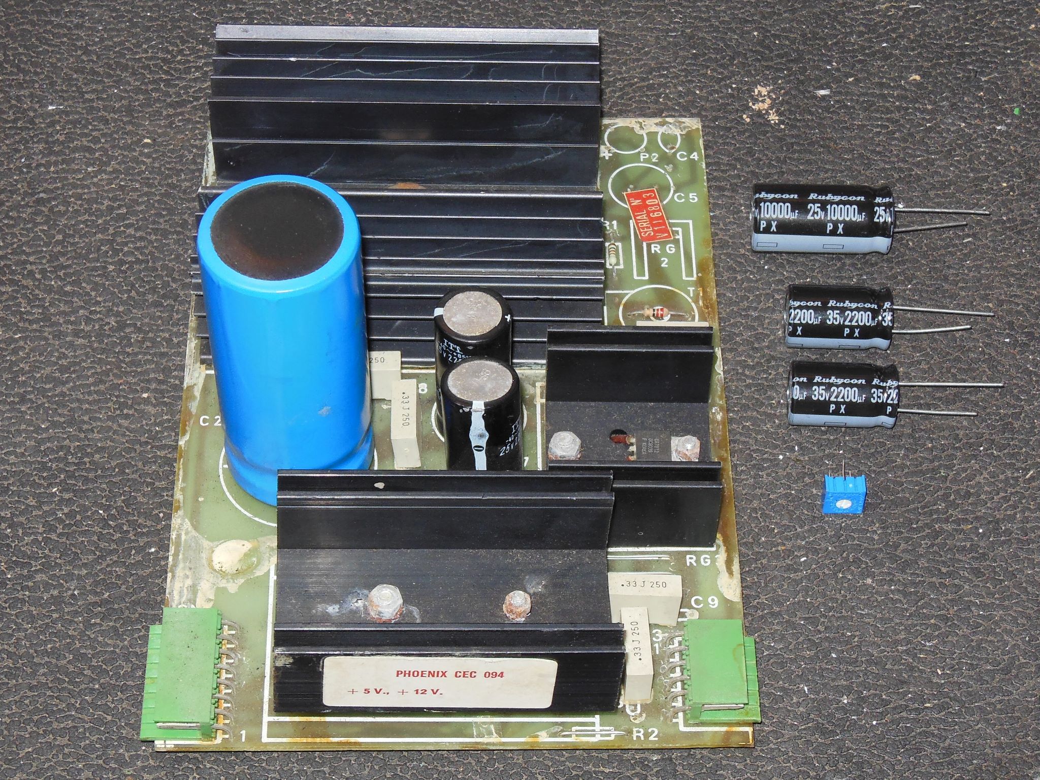
I was seeing an occasional reset of the game and suspected a power regulation problem. The large blue capacitor on the regulation PCB had a "hot spot" in one area near the top so I decided to fit a cap kit. After the cap kit the game ran for several more hours with no issues, ready for show time!
|
During pre-show testing I noticed that some of the game sounds weren't quite right. I removed the game PCB to test on the bench and repair.
|
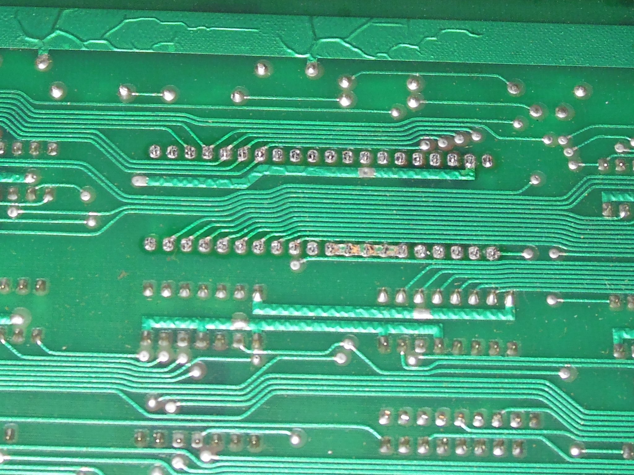
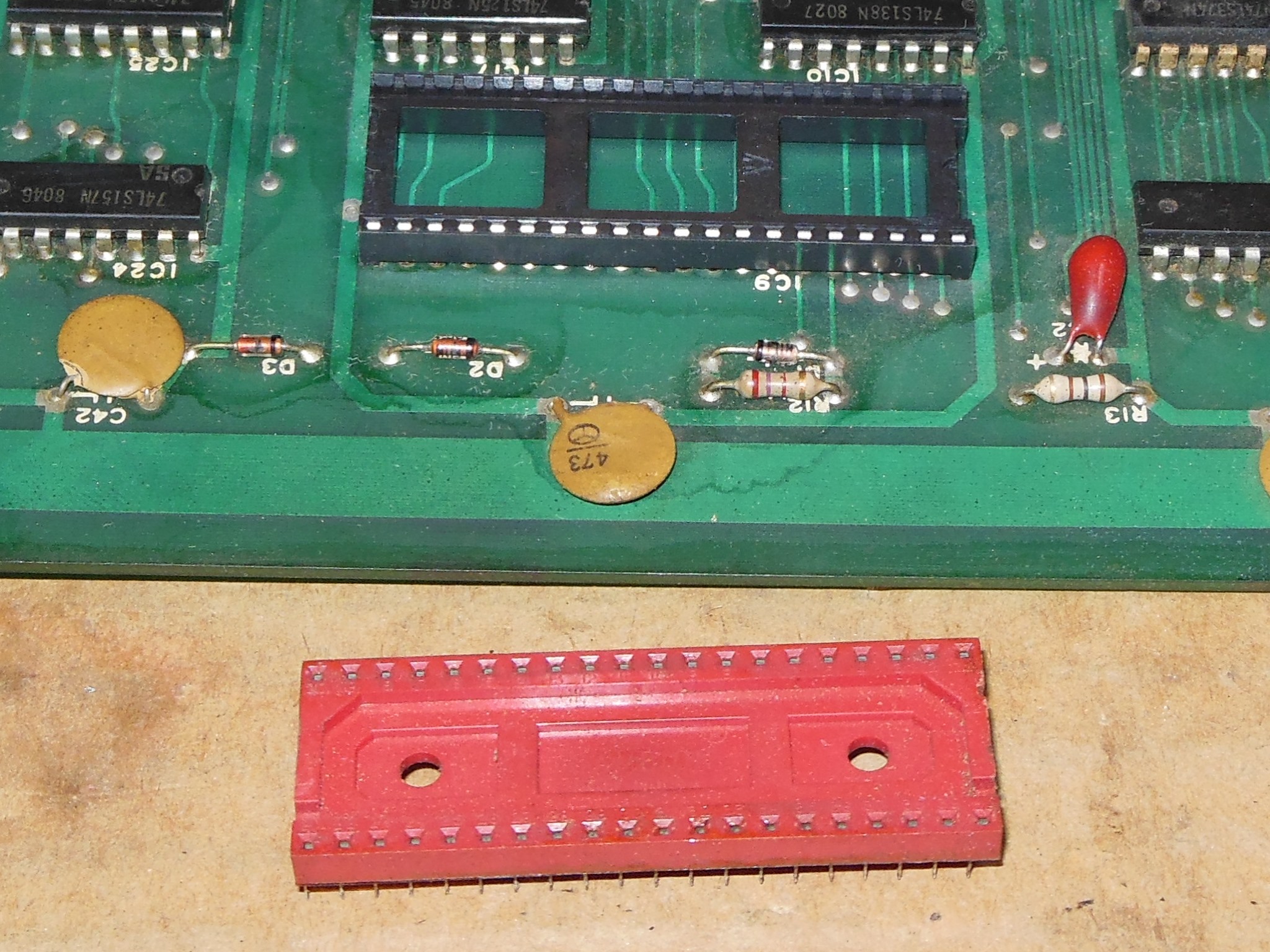
The game starting having crashing issues on the bench. Since it had the notoriously bad red Cambion socket I tried pressing on the 8085 and it did indeed cause crashing problems. I don't use the vacuum de-solder gun often but for large pin count sockets it's a time saver. With a new socket fitted the board was running reliably again and I resumed investigating the sound issue with the Arduino ICT.
|
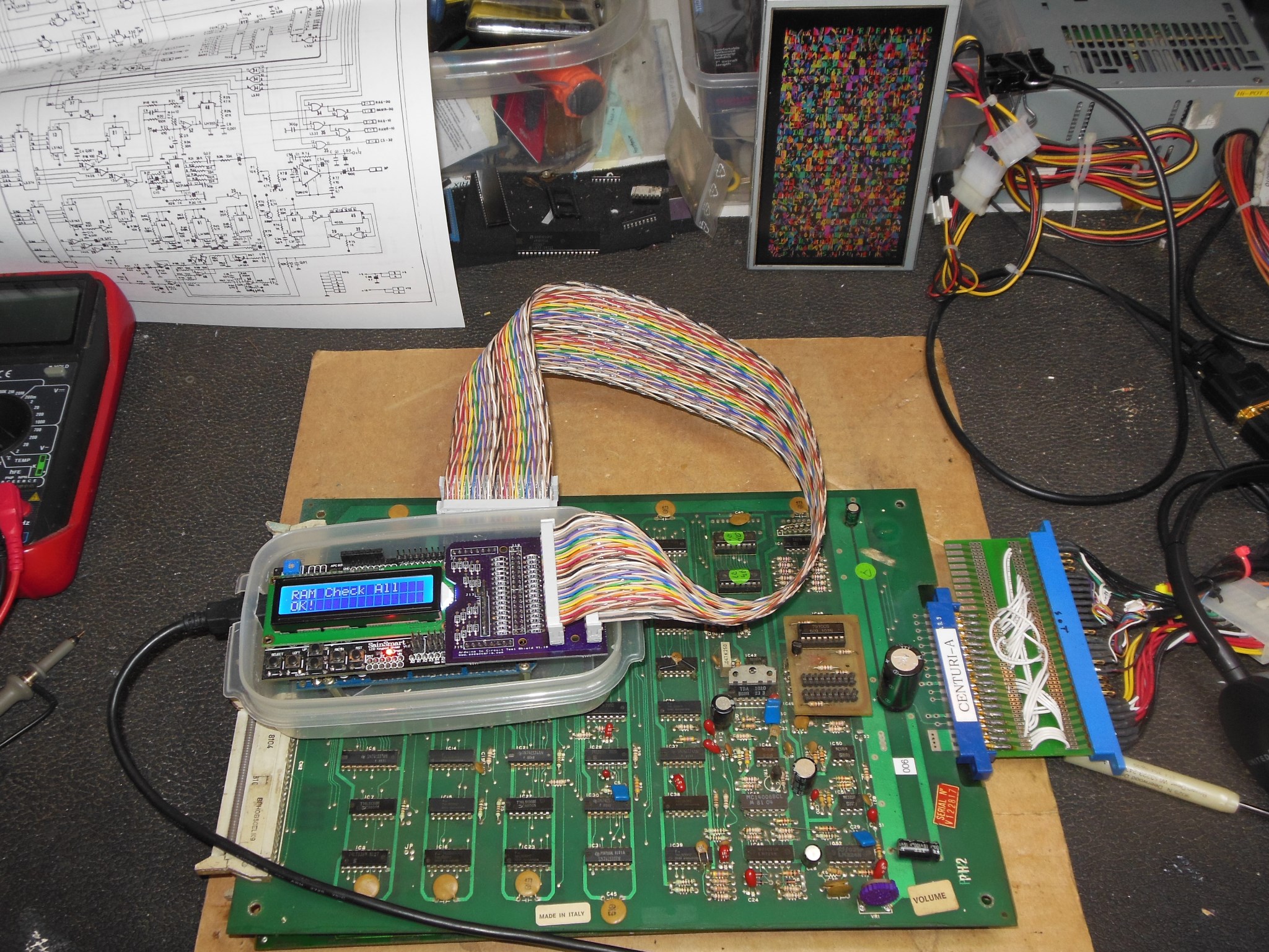
The first challenge was figuring out how the component sounds were supposed to
sound. The Arduino ICT allowed the component sounds to be triggered but without a
reference on what the components sounded like I couldn't easily tell which was the one
not working correctly. I decided to first record all the component sounds from
the spare known good working GGI board to compare with the faulty Zaccaria PCB:-
Phoenix Sound Recordings
I'd just managed to complete all the recordings before GGI PCB died on the bench :(
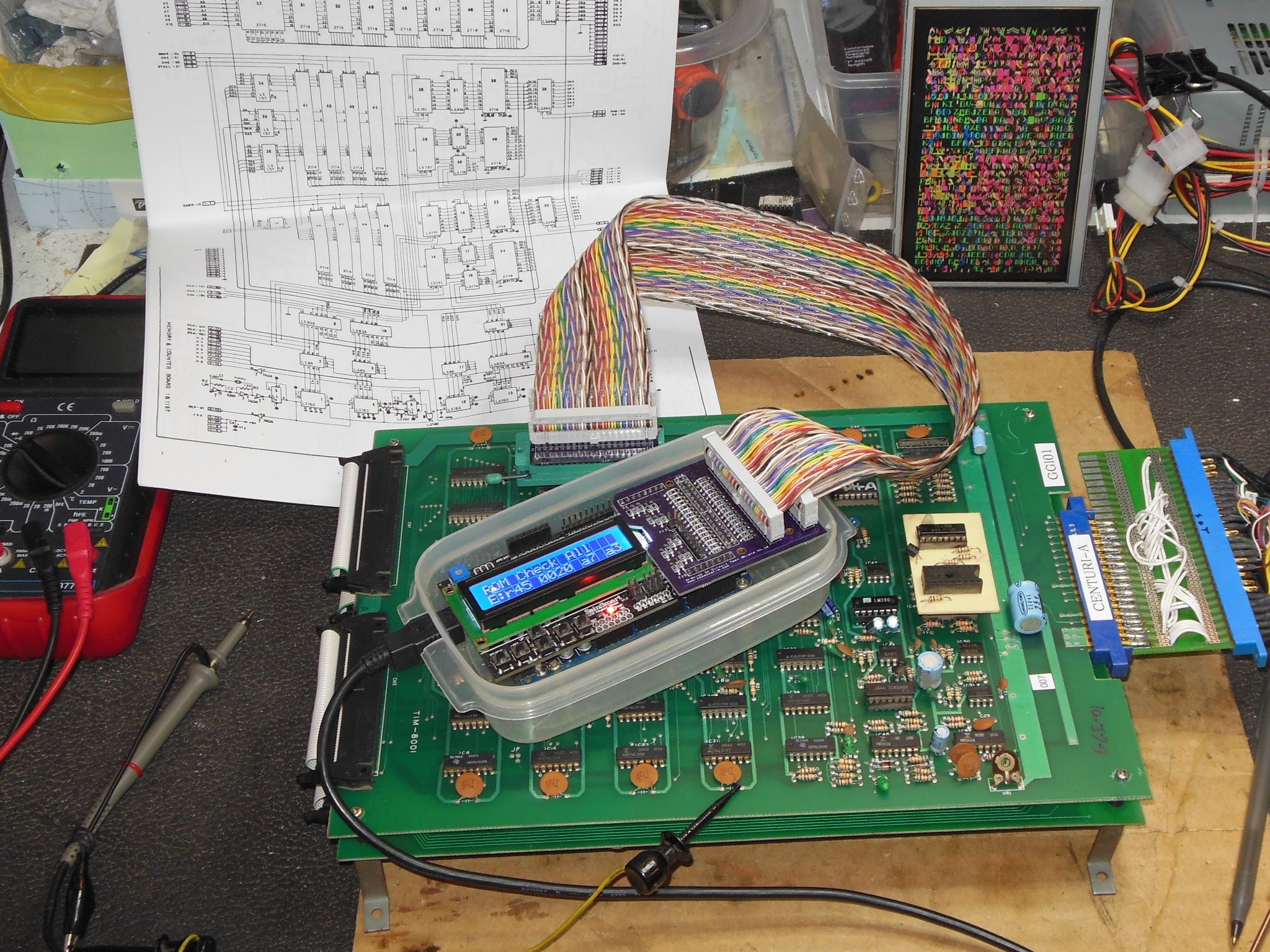
The GGI PCB failed to boot at all and the Arduino ICT reported all ROMS bad in some
form:
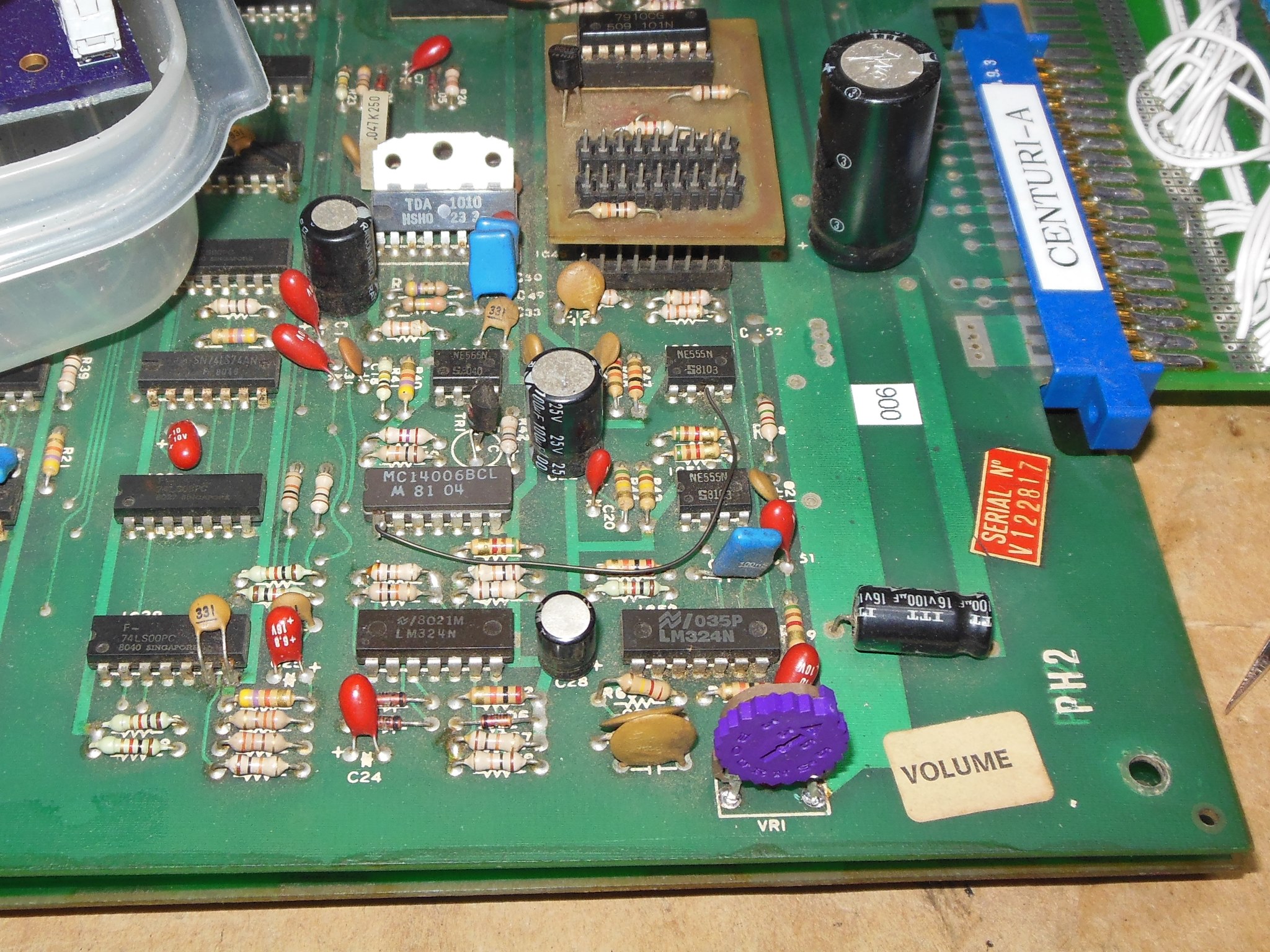
Moving back to the Zaccaria PCB I compared the component sounds with the reference recordings to isolate "SCntA8" as missing some sort of envelope. Checking IC 50 (555) pin 3 found a 20KHz signal. Checking IC 51 (555) pin 3 found a slow pulse. Checking IC 44 (555) pin 3 found it was always high as was pin 2. Triggering "SFrqA1" and checking IC 29 (LS05) found pin 13 input toggling and pin 12 output low. I noted from the schematics that this was AC coupled to IC 44 pin 2 and for there to be any effect there would need to be an oscillating signal on pin 2 of IC 44 (555) to pull to ground through the capacitor. I suspected IC 44 was bad and replacing it fixed "SFrqA1" and the game sounds were now correct.
Back in the cabinet the game played and sounded OK.