|
|
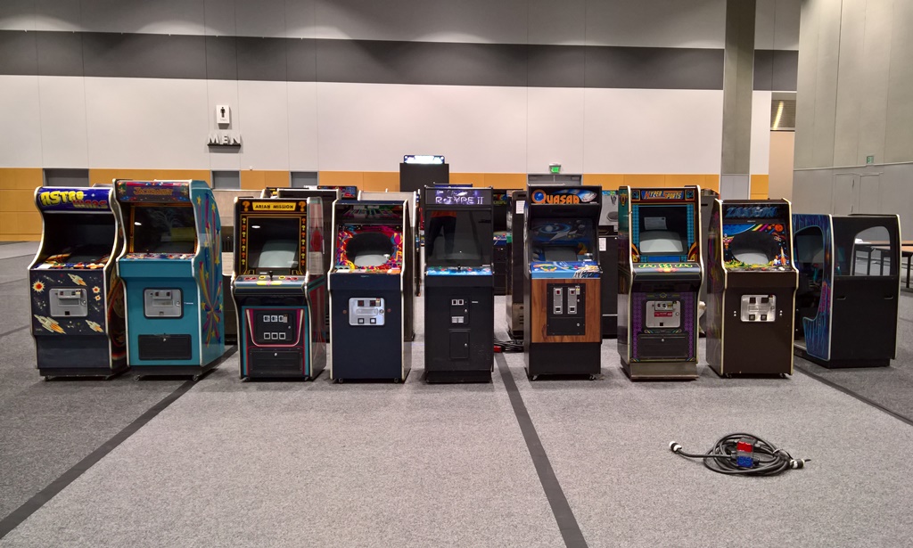
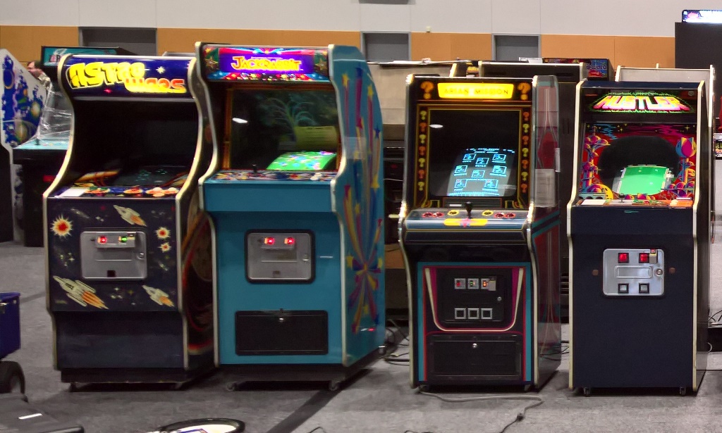
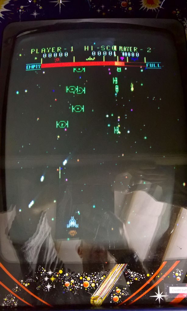
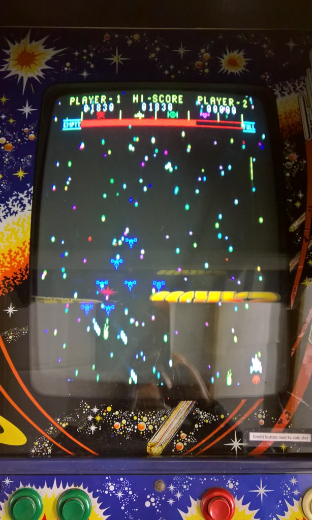
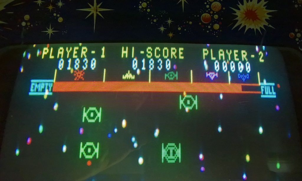
The game made it to the show and initially was working OK on power-on on Thursday. After a few hours, however, the game started to have hang & crash issues. I brought a spare untested game board with me on Friday to swap into it but by then the monitor was also dead :(
|
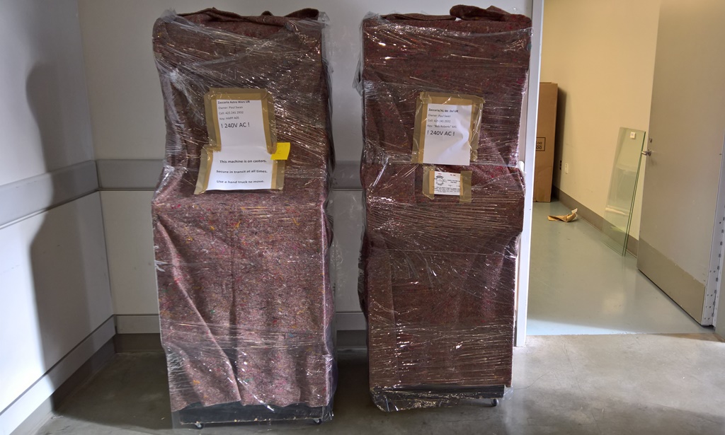
The game was wheeled into the back room and repacked for return :(
|
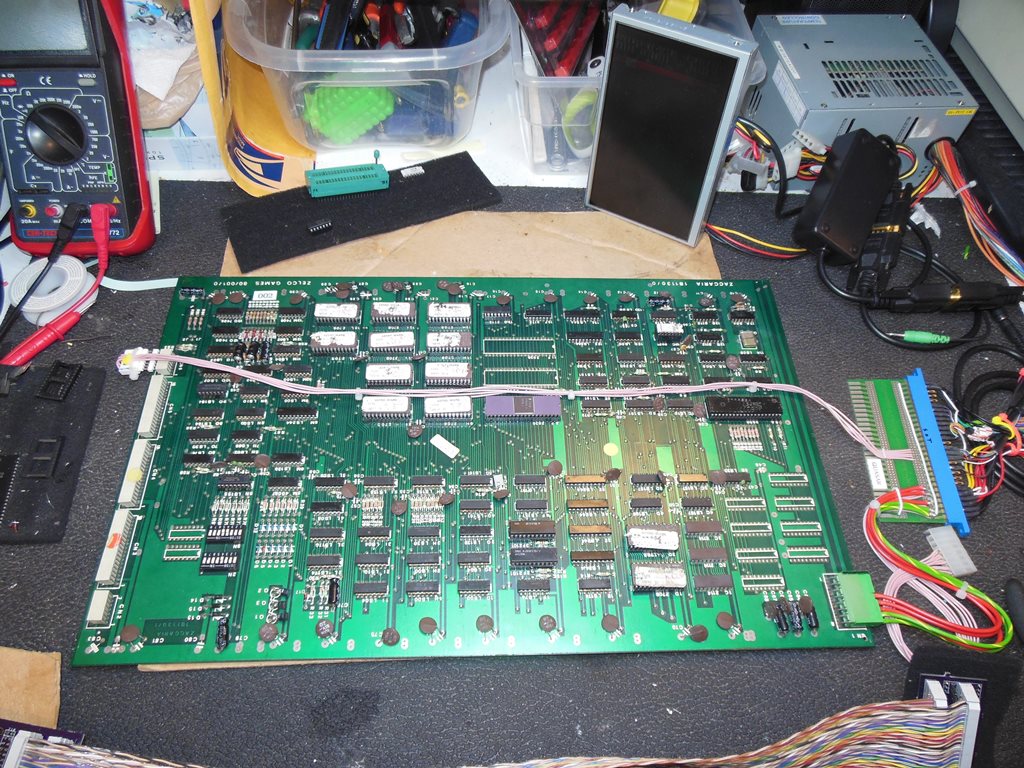
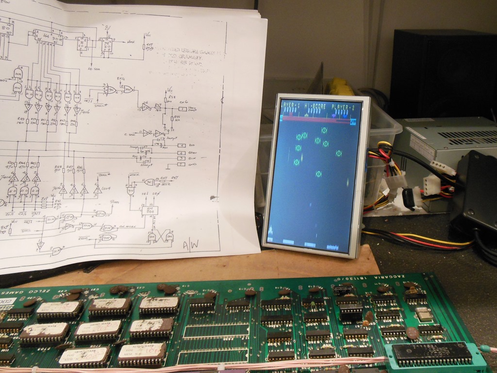
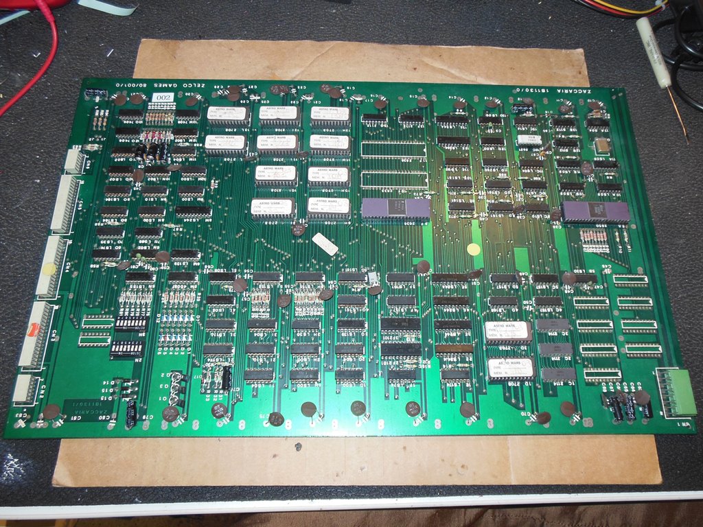
On the bench the PCB exhibited the same issue as in the cab - graphics messed up and crashes/hangs in attract mode. Testing with the Arduino ICT didn't flag any RAM or ROM issues in the basic test but the extended "RAM Test RA" test flagged "13? 14B7 01 08" suggesting the 2112 RAM in the low nibble, IC 13F, was bad. A quick piggyback check appeared to confirm the RAM was bad. Replacing IC 13F (2112) fixed the game.
|
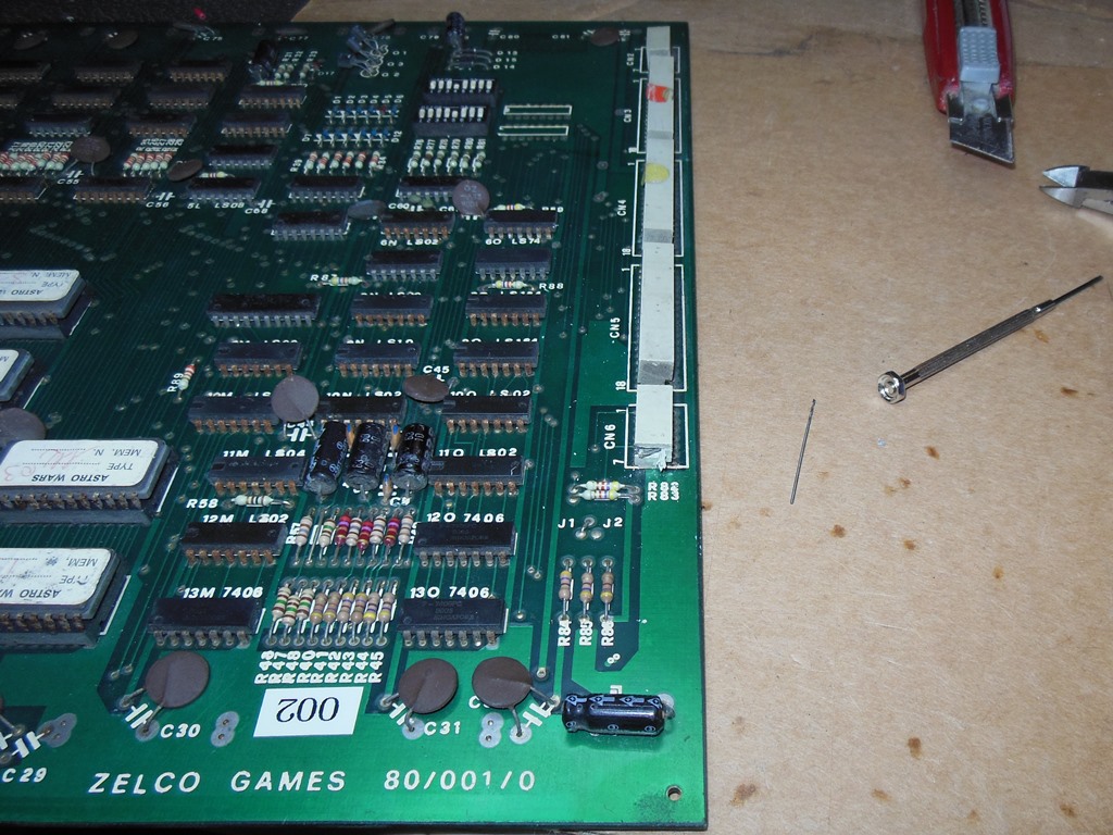
Since I had no known good working spare Astro Wars game PCB, I decided to repair a second board as a backup (in fact, I decided to put together a "Show Spares Box" with spare/backup game boards for all the games currently running). I had a few untested Astro Wars game boards but all of them had corroded sockets at least. I picked the best of the bunch to start with.
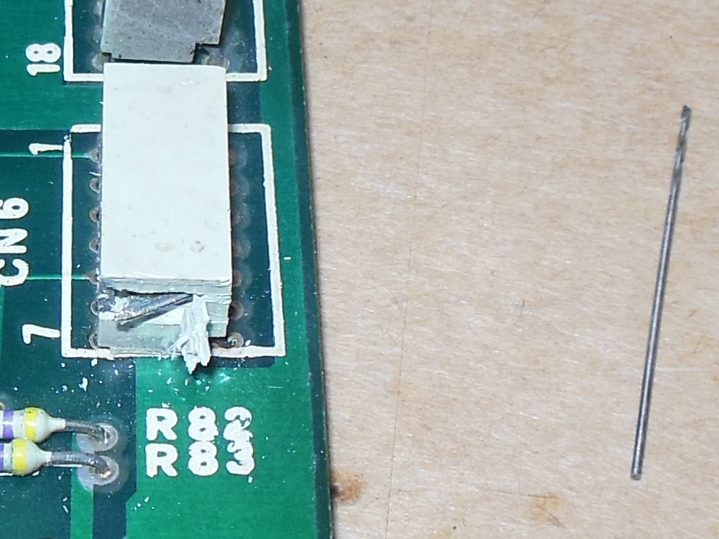
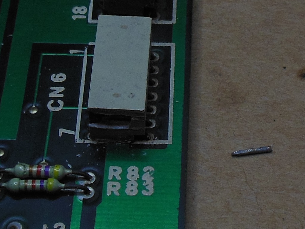
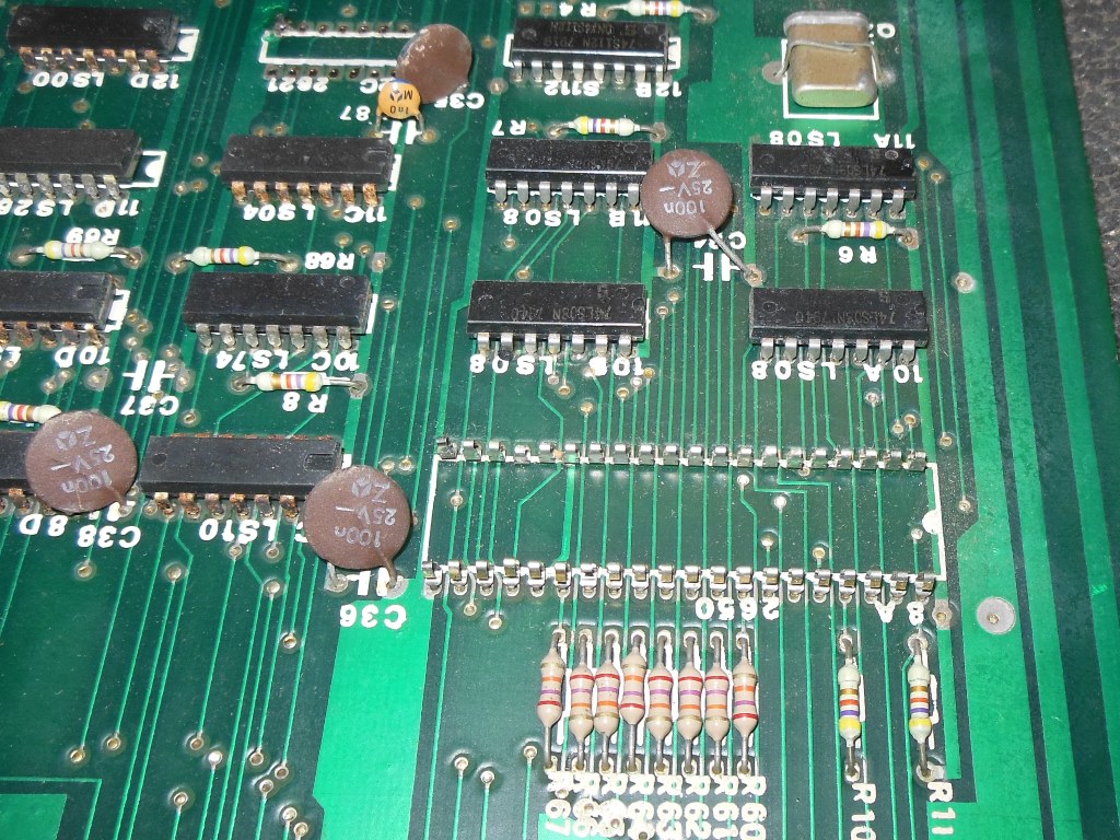
The first problem to sort out was that the video connector couldn't be plugged in because a broken pin was wedged into the PCB socket. This type of socket is long since out of production and I hadn't found any source for NOS ones. Since the broken pin was in the last socket of the row, I decided to try to open up the side of the socket to remove the pin. Using a craft knife I removed a small section of the side wall and was able to retrieve the broken pin. The socket appeared to be otherwise undamaged.
|
|
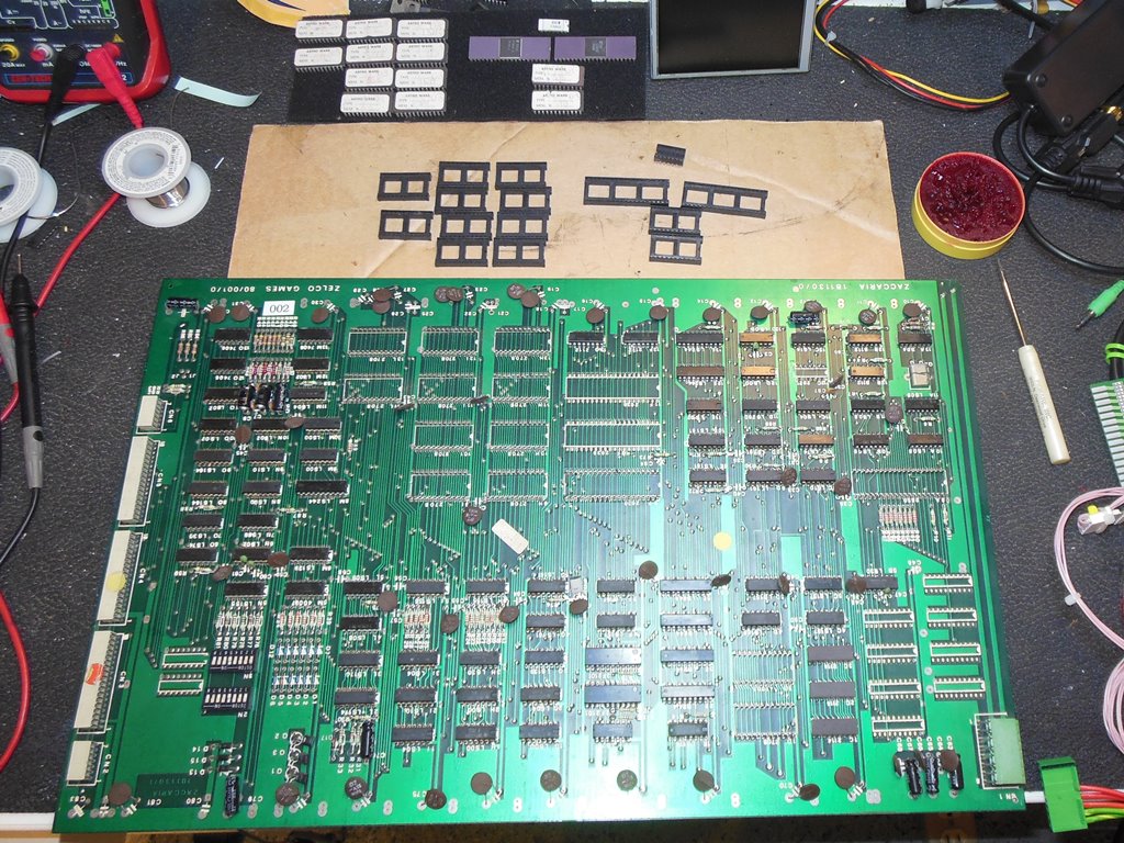
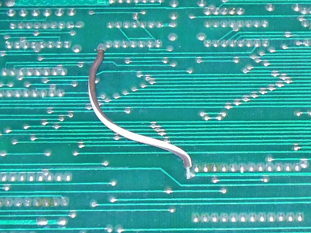
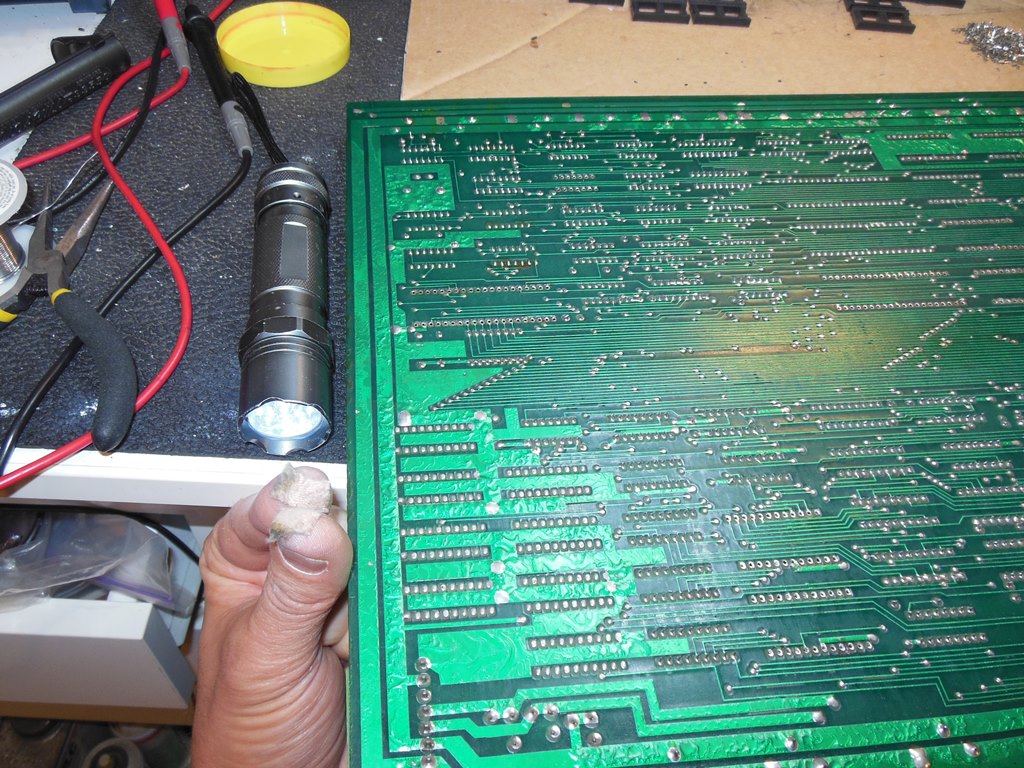
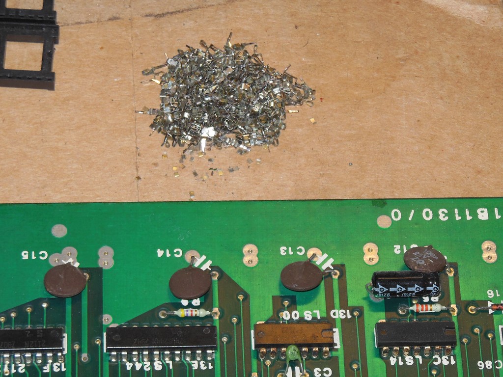
Initial inspection found many loose sockets and a few broken pins on the EPROMS. It was clear that all the sockets on the board would need to be replaced. Thankfully the board used Augat sockets that are easy to change out - lever off the plastic body, remove all the pins and then vacuum de-solder all the holes to leave a clean finish for new sockets to be installed. There are a lot of sockets on this game board, so I stuck two small moleskin pads on my finger tips to allow quick and easy finger pulling of pins. I also made a note of where the wire strap is fitted, since it would need to be disconnected for the socket replacement. The EPROMS with broken pins I replaced with ones from another poorer condition spare board.
|
Testing with the Arduino ICT flagged a several issues. Firstly a "13G 1400 90 30" flagging IC 13G (2112) RAM as bad. Replacing the RAM cleared the error. Next up was an intermittent "3F 1C00 01 0F" and hard "2F 1C00 90 F0". On the scope the D outputs of IC 2F (2101) looked bad. Replacing IC 2F (2101) cleared the error. I set aside the intermittent error on 3F for now.
|
|
On power up with a 2650 CPU the game generally ran but with issues:
* Missiles were not correct.
* The stars looked bad.
* The collision detection didn't appear to be working.
For the stars problem, poking around the a scope suggested IC 9O (74LS164) may be bad.
Replacing IC 9O (74LS164) appeared to restore the stars. For the missiles problem,
changing IC 3F (2101) appeared to fix the missiles however the Arduino ICT still
intermittently flagged a bad IC 3F RAM.
Debugging the collision detection issue was a bit more involved. Collision read pulses were present on IC 8M (74LS244) pins 2 & 4 OK. Using two channels on the scope also suggested collision data was being read on DB1 & DB0 OK. With the ICT collision detection with missiles at least seemed to be working OK. Attention turned to the DIP switch that controls collision detection (the game has a test switch that turns off collision detection, so I suspected the read of the DIP switches may be bad). Reading the DIP switches with the ICT returned 0x0C all the time, no matter what the settings were. The ~EXT pulse looked OK however the outputs of IC 5N (74LS155) had poor logic high. Replacing IC 5N (74LS155) fix the output logic levels and also fixed the DIP switch read data & game collision detection.
There was still some odd intermittent behavior with the ICT - "RAM Read All" and "ROM Read All" would sometimes cause the displayed graphics to be affected/corrupted. Retesting with the 2650 CPU didn't show any problems, but I wanted to test the game more fully and that needed a control panel...
|
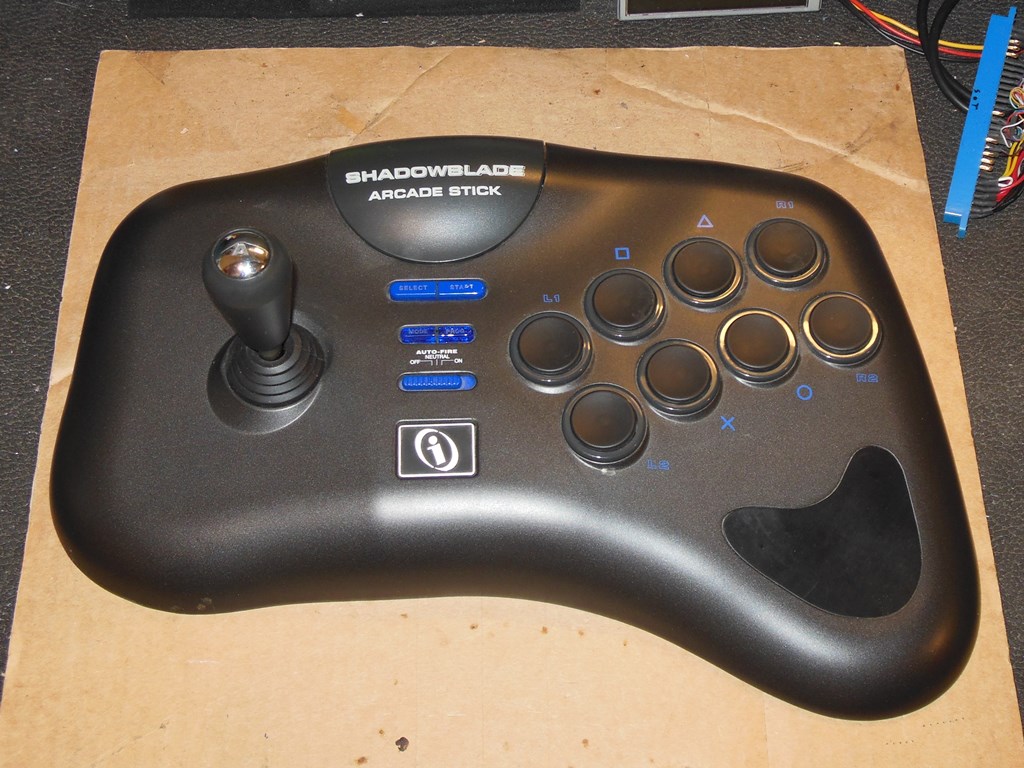
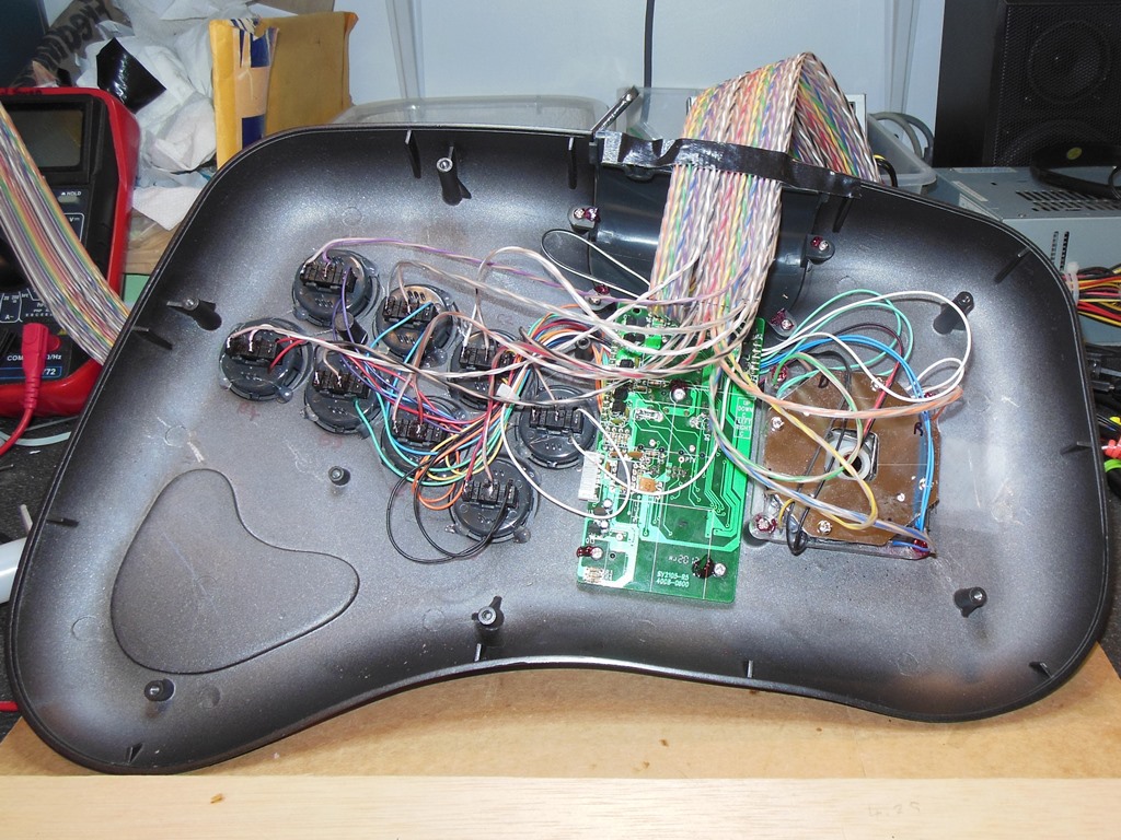
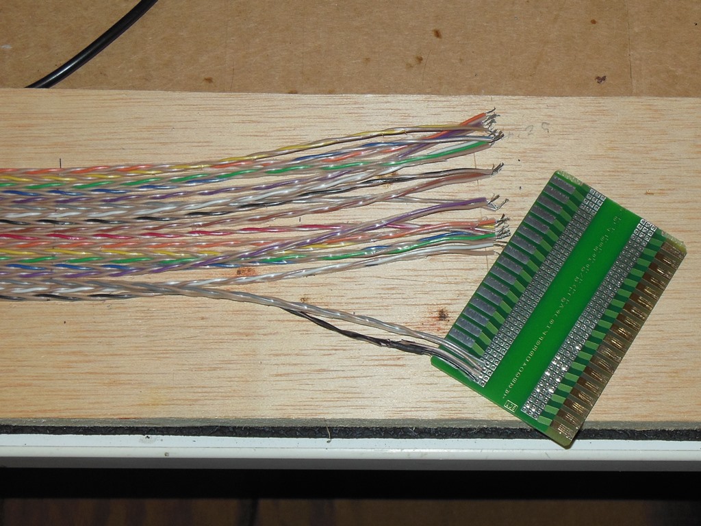
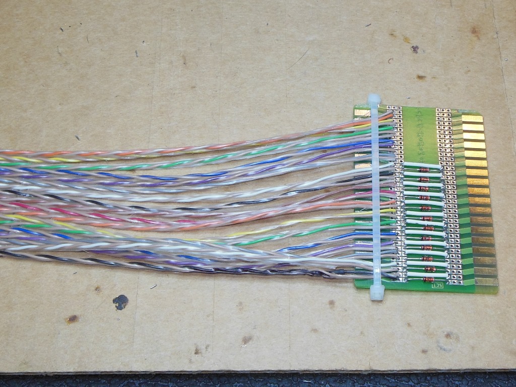
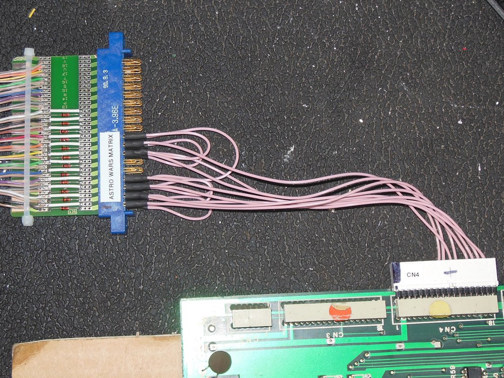
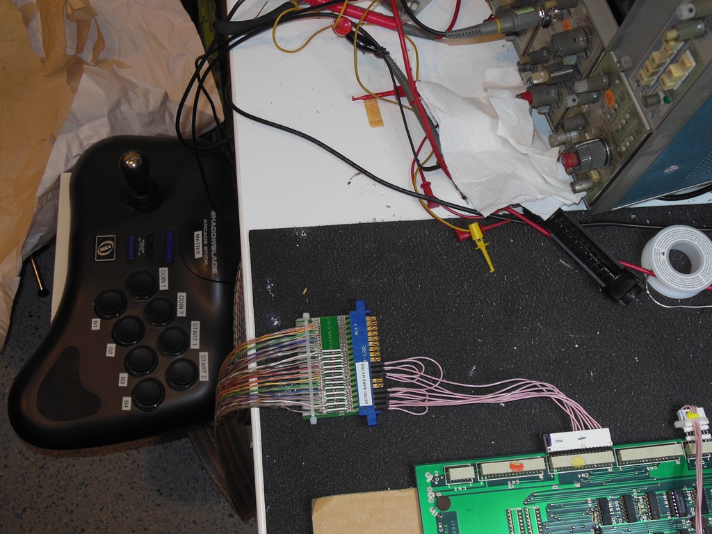
Up to now I'd managed to avoid building a control panel for the Zaccaria matrix input configuration. Since I was bringing up a new game PCB and I would otherwise have to put in the cabinet for final play testing I decided to bite the bullet and convert an unused PlayStation arcade control panel for use with matrix games. The idea was to route out both sides of every switch via a wide ribbon cable to a finger board that would hold the diodes. Each game would then have a simple adaptor to connect them to the matrix control panel.
|
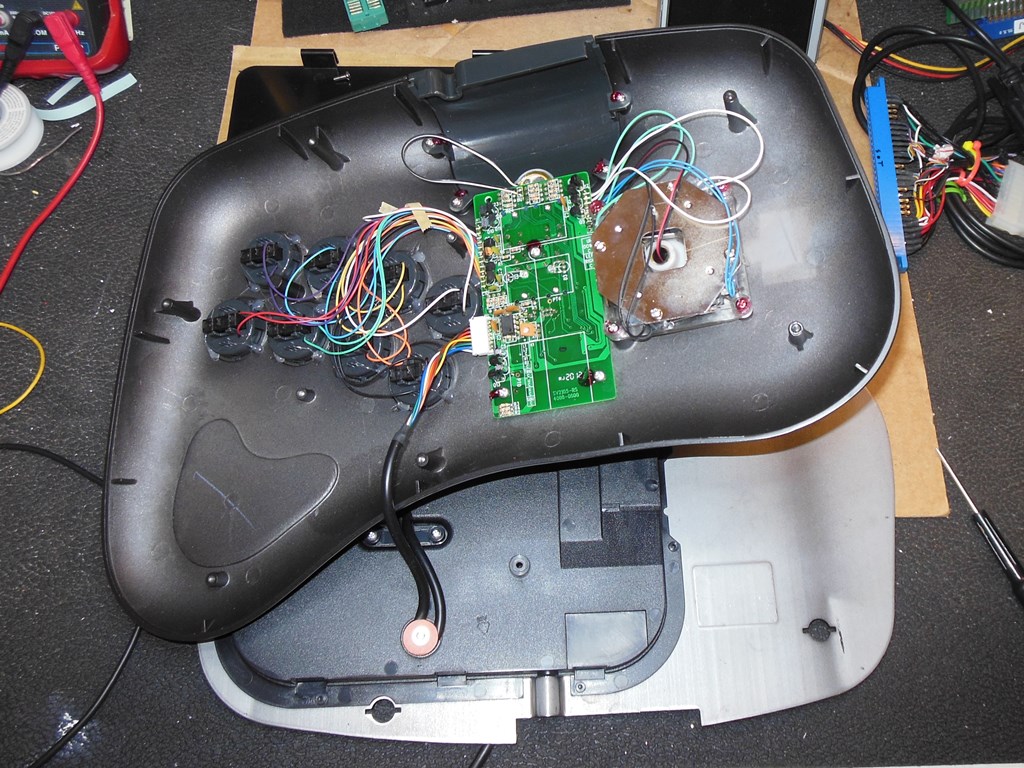
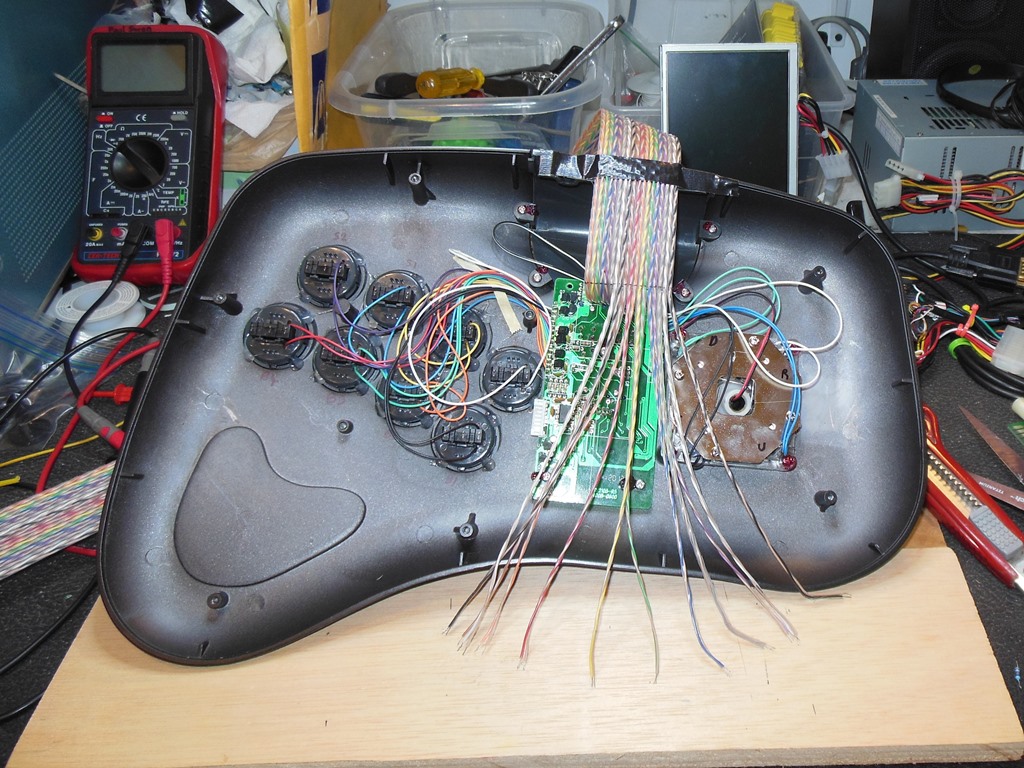
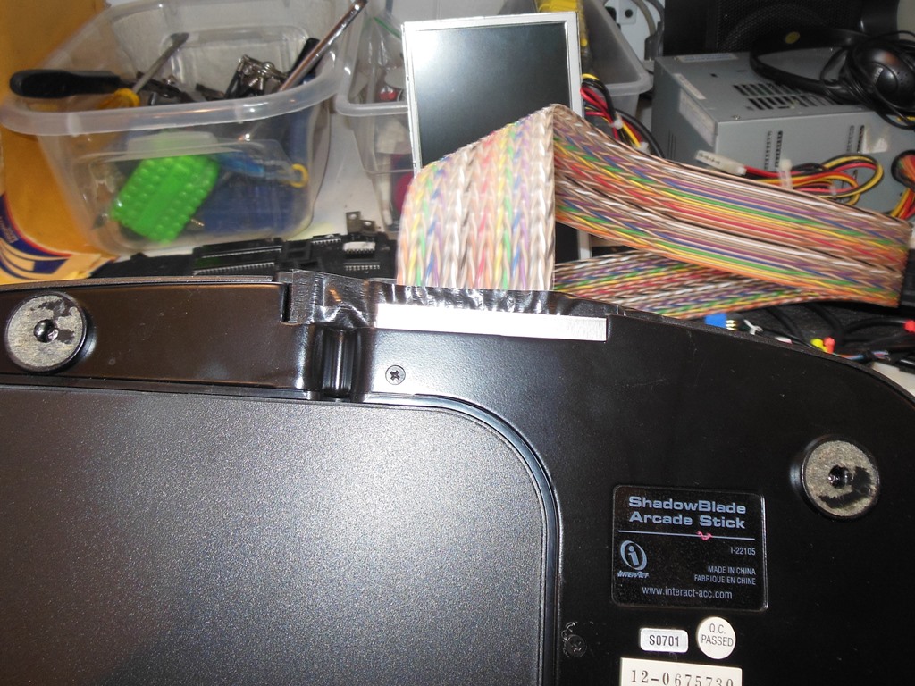
The design of the buttons on the Shadowblade panel was such that each switch had both a microswitch contact and a hall effect contact. The existing PlayStation inputs used the hall effect contacts so no big de-soldering or cut-out was needed. The matrix ribbon could be attached to the unused microswitch contacts. The ribbon cable was then sandwiched between the base and the cover using a small metal plate for strain relief.
|
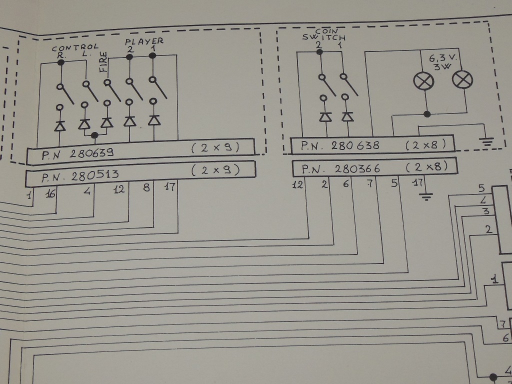
The pinout was chosen to be the JAMMA running order for the inputs, using 12 pins of
the 18-way connector, supporting up to four buttons as used by Lazarian:
| Coin 1 | + | 1 | -->|-- | A | - | Coin 1 |
| Coin 2 | + | 2 | -->|-- | B | - | Coin 2 |
| Start 1 | + | 3 | -->|-- | C | - | Start 1 |
| Start 2 | + | 4 | -->|-- | D | - | Start 2 |
| Up | + | 5 | -->|-- | E | - | Up |
| Down | + | 6 | -->|-- | F | - | Down |
| Left | + | 7 | -->|-- | H | - | Left |
| Right | + | 8 | -->|-- | J | - | Right |
| Button 1 | + | 9 | -->|-- | K | - | Button 1 |
| Button 2 | + | 10 | -->|-- | L | - | Button 2 |
| Button 3 | + | 11 | -->|-- | M | - | Button 3 |
| Button 4 | + | 12 | -->|-- | N | - | Button 4 |
|
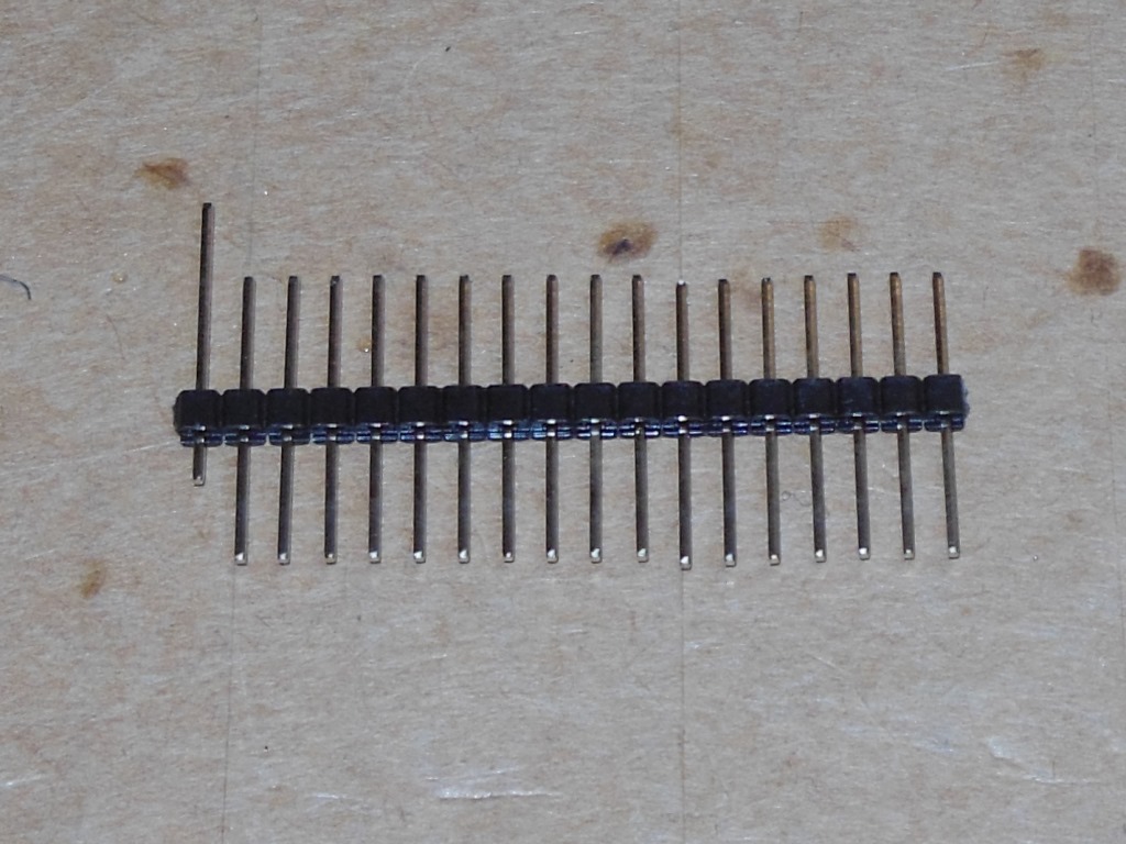
The Astro Wars adaptor was constructed using a traditional female connector along with a 19mm SIL header with the pins pushed through half way to act as a gender changer for use on Zaccaria female PCB connectors.
|
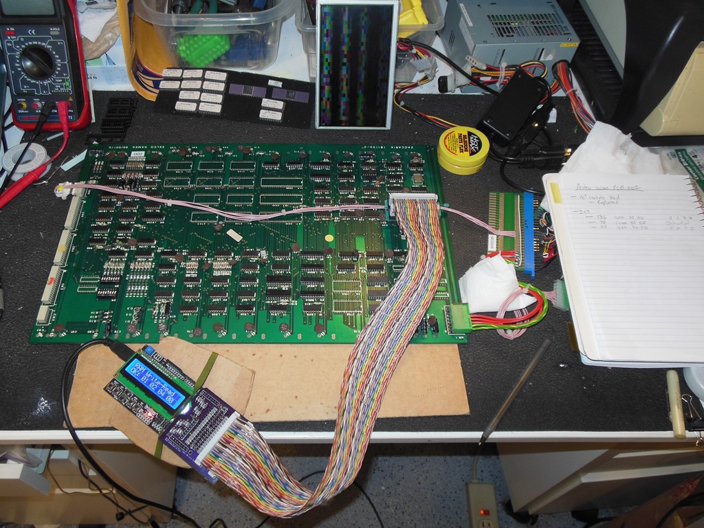
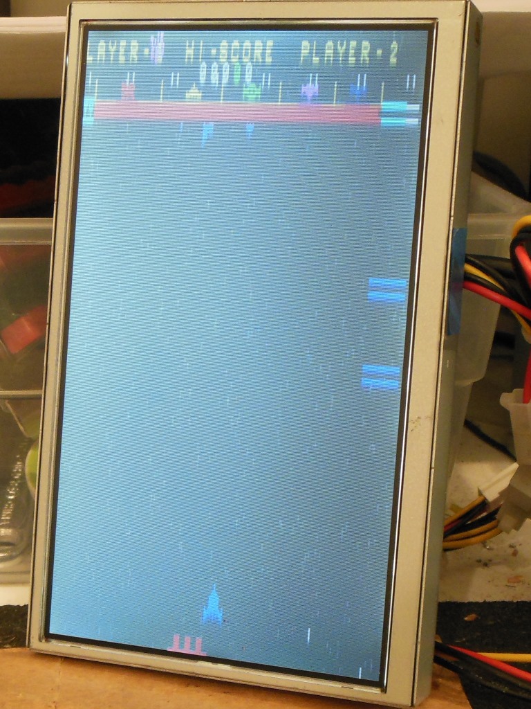
In use the control panel worked fine with no issues. Finally I could play test Astro Wars on the bench :)
With the newly constructed control panel the game inputs could now be properly tested. Everything seemed to be working OK - coin 1, start 1 & 2, left, right, fire - except the coin 2 input had no effect (didn't coin the game). The coin 2 input was OK up to IC 5M (40097) so a bad IC 5M was suspected, set aside for now.
Throughout testing I continued to have intermittent issues. First graphics and colour corruption, then no boot. With the Arduino ICT all tests passed and there was no graphics corruption (previously seen on the ICT, but now no longer present). The interrupt check on the ICT also went through periods of failing and then passing. This sort of intermittent issue is tough to work through :(
I began seeing unstable video graphics again with ICT so I quickly dived in with the scope whilst the symptom was occurring. I caught poor logic levels (< 2V) on IC 1D (2708) pins 1 through 5. Working back IC 4C (LS157) pin 4 (output) was unstable but pin 3 (input) was OK. The control pin 1, ~SAB, hovered around 1.2V rather than active low. IC 1C (2114) pin 8, ~CBG, was also unstable. Working back further found IC 1I (LS04) pin 10 -> pin 11 both intermittent. IC 2I (LS10) pin 5 was solid high, pin 4 solid high and pin 3, VRST*, intermittent. The bad VRST* signal could also explain the failed interrupt test on the ICT. Checking IC 13C pins 3 and 4 looked OK, in fact all of 13C looked OK such that VRST & ~VRST were good. Zeroing in on 11E (LS02) found pins 1 & 4 looking bad, pins 2 & 3 looking OK. In fact, most of 11E outputs looked bad, and I suspected it was bad. Finally, changing 11E (LS02) and 5M (40097) fixed the unstable video, interrupt test fault & missing coin 2 input.
Alas, this wasn't the end of the repair. Though working much better the game would still hang, freeze or suffer graphics corruptions. The interrupt circuit looked OK. Replacing the 2636 had no effect. Poking around the chip selects didn't find anything obvious. With the Arduino ICT all sub-systems were passing OK. I left the game running on the bench for 12hrs in the hope of making an intermittent fault permanent. I wasn't disappointed - the game stopped booting. The Arduino ICT still wasn't able to detect any problem :( I did see cases where the ICT ROM check caused video interference. IC 2C (2114) pin 11, B3, saw data active on ROM check. Shorting B3 to B2 (pin 11 to 12) caused the ROM check to fail. This indicated that the video data bus was active on the processor bus when the ROM check ran. IC 3C (2114) pin 12 was also active when the ROM check was running. It appeared that the problem was only with this pin so I suspected a bad IC 3E (LS244). However changing IC 3E didn't change anything :(
The characteristic was still no boot, still ROM read data present on B3. The ICT passed "RAM Write AD" and on "ROM Check" I saw 2636 graphics and CRC failures on IC 8H (2708). I suspected a bad IC 4E (LS244). Changing IC 4E (LS244) didn't change anything. I set aside the game to work on Arduino ICT improvements to better target this issue (improved 2650 timing & the addition of a "Soak Test" option).
With new Arduino ICT features in hand it was time to start looking at it again. Soak testing with the ICT didn't hit any issues, however with a 2650 running the game it still crashed on boot. During testing, full screen red flashes started occurring, seemingly unrelated to the boot problems. On the scope, the red flashes were detected on pin 8 of IC 13M (7406). Pin 9 of IC 13M looked OK. Pins 1 and 3 of IC O13 (7406) exhibited the issue. Pin 33 of IC 8F (2636) showed the issue but pins 34 & 35 did not. With a new 2636 the issue was still present. I suspect an input to output short on IC 11O (LS02). Replacing 11O (LS02) fixed the red flashes.
Looking into the intermittent hang/crash issue with improved Arduino ICT timing for the 2650 finally caught a break with solid repro of a ROM read fault, returning 0xFF. I quickly set about tracing it whilst the issue was present in case it was lost again. IC 12E (LS244) pin 19 (~RCOD) was sometimes floating and then jumping high after the cycle ended. IC 2G (LS04) pin 13 looked OK but pin 12 looked bad. I suspected a bad IC 2G (LS04). Replacing IC 2G fixed this issue and the game was finally running OK :)
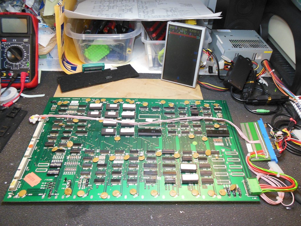
The board remained on the bench for a week or so whilst we were on holiday. On return I planned to begin some long term bench testing to make sure the game was finally solid. Alas, on first power on after the break, the game didn't boot again. The ICT failed the ROM checks on almost all the ROMS (only 13H, 11I, 13I & 11L passed). Checking the address & data lines on the EPROMS with the scope found IC 8H (2708) pin 23 (A8) floating at 2V. IC 3G (LS139) pin 2 (A8) also showed floating so it wasn't an open track or pin. IC 11A (LS08) pin 3 output was floating with good input so I suspected a bad IC 11A. Replacing IC 11A brought the game back to life yet again. Subsequent burn in testing on the bench for many hours over several days turned up no further issues.
|
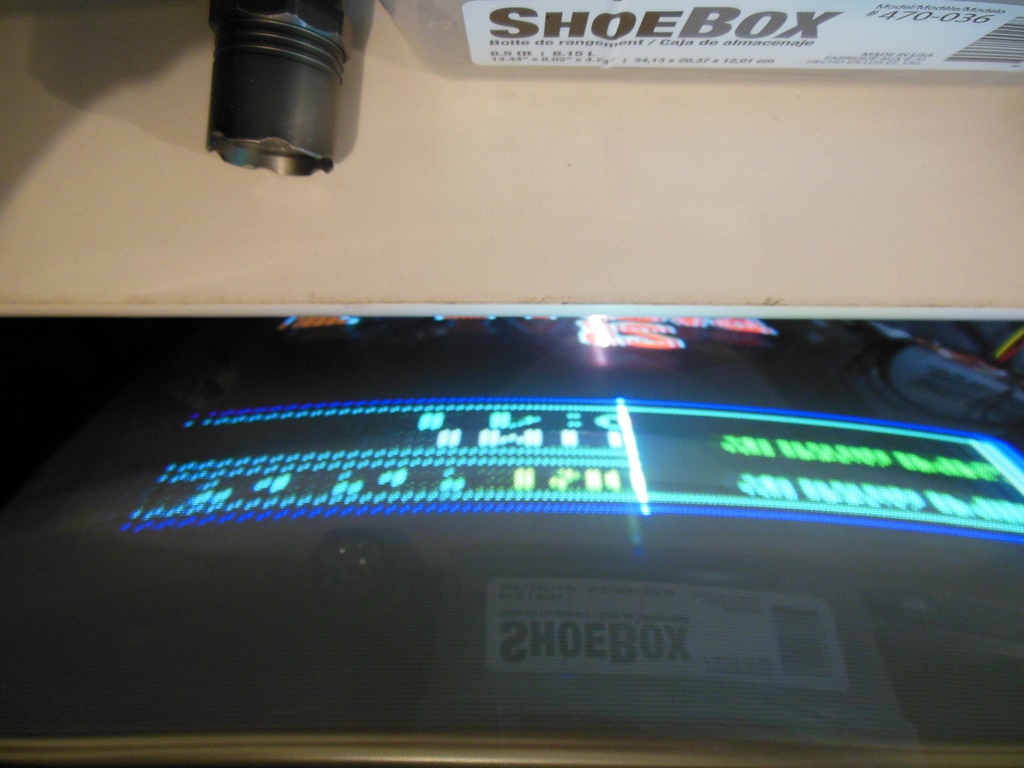
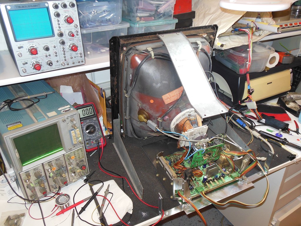
At the show the monitor didn't start and there was no picture. Back home sometimes it started and sometimes it didn't. On the occasions it did start the picture had geometry issues.
|
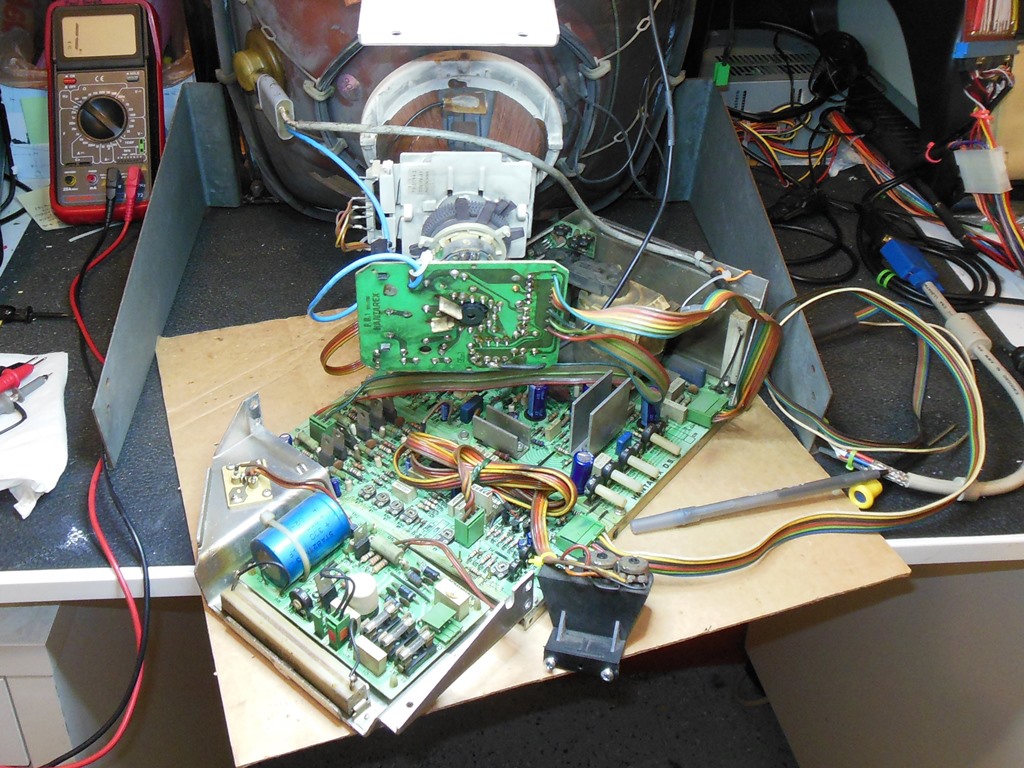
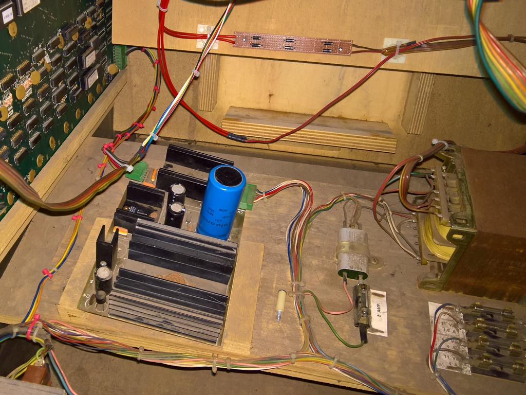
On the bench, the picture was generally unstable with intermittent partial vertical collapse and unstable horizontal size I'd seen this type of problem before caused by B+ regulation issues and I wasn't disappointed this time - the B+ measured a variable 105VDC to 109VDC versus the required constant 126VDC. I've personally found the quickest way to fault find the regulator board is to simply remove the transistors and Hfe test them. I selected TR7 (BC337) to start with and it tested bad. Replacing it with a new BC237A (per manual) fixed the regulation, restored B+ to 127.5VDC and the picture was back to normal.
|
|
With fixed game PCB and fixed monitor chassis back in the cabinet the game was working fine and stayed working for a few hours, ready for the next show (fingers crossed again).
|
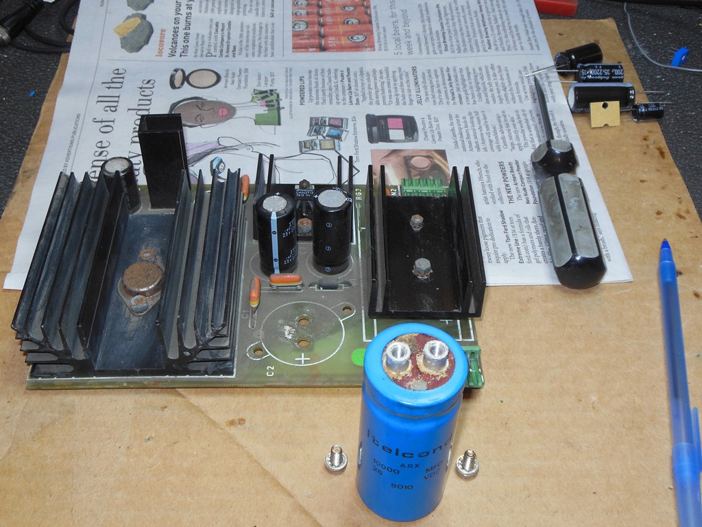
Pre-show testing found the game failing to boot with uneven brightness on screen that was isolated to fluctuating +5V on the power regulator board. The power regulator board was generally corroded and I removed it to inspect on the bench.
|
Unscrewing the large +5V smoothing capacitor found it leaking & corroded around the screw terminals, confirming the need for a cap kit.
|
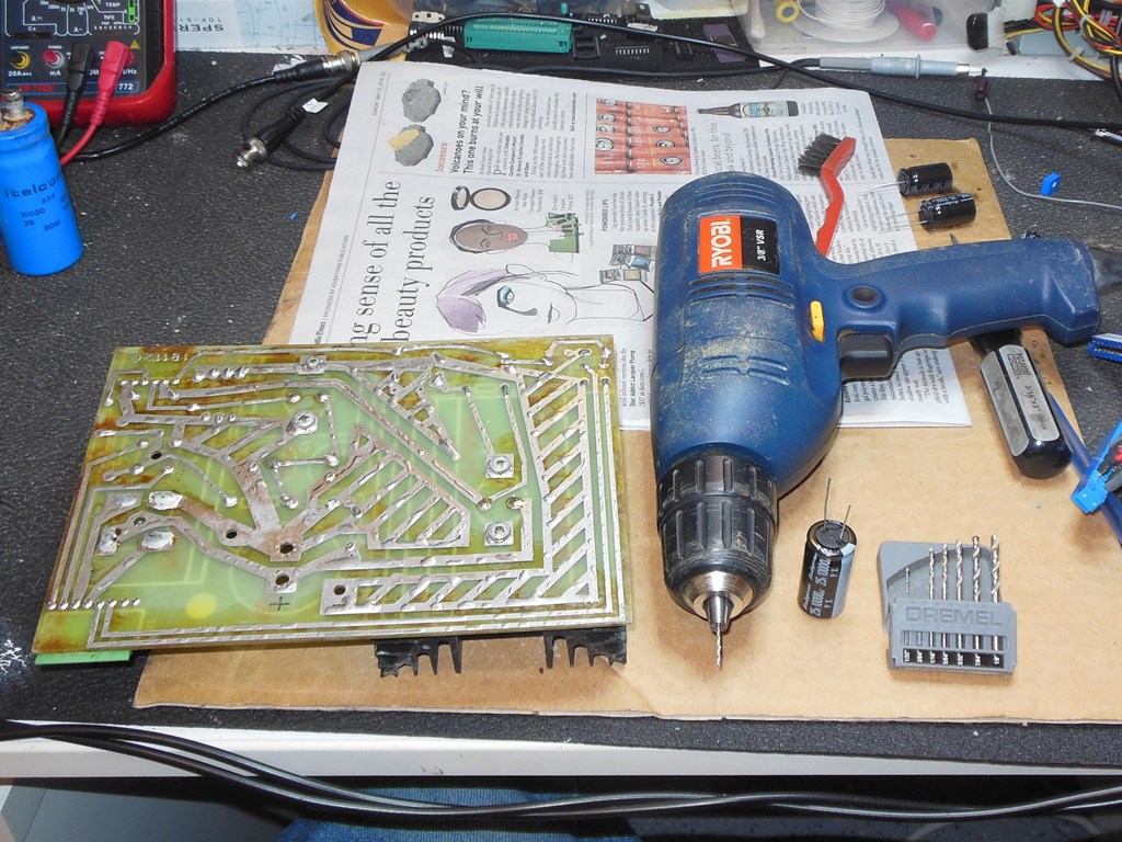
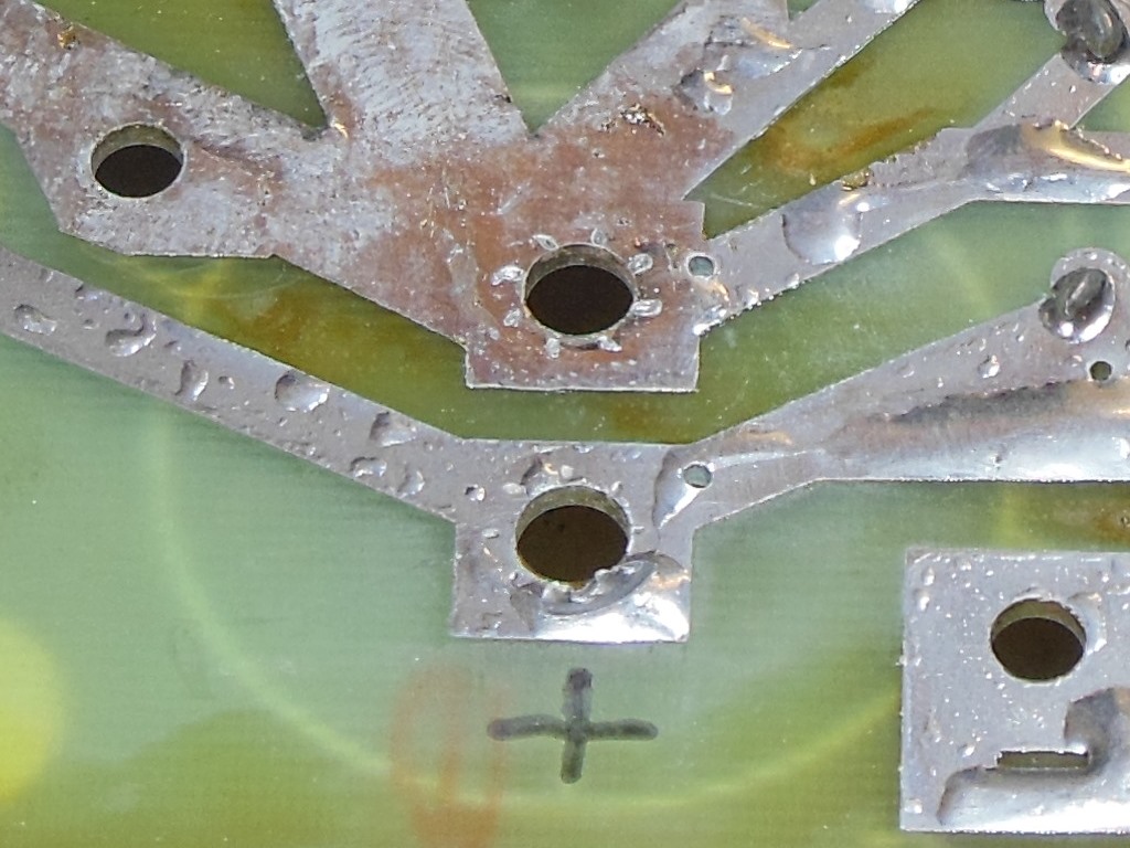
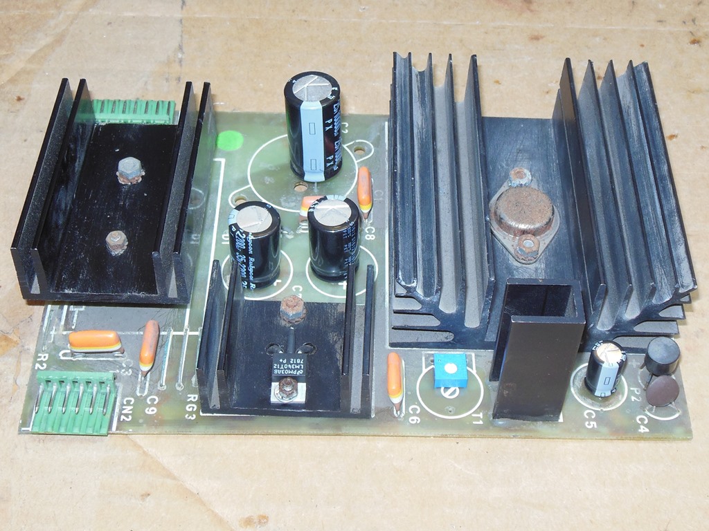
As an early example of the 1B1126 it didn't have the extra holes to allow for a through hole capacitor instead of the screw terminal type. A fine pitch drill bit was used to put in the two through holes and complete the cap kit. The connector pins for power input and output were also gently cleaned with a wire-brush Dremel.
After the cap kit and contact cleaning, back in the cabinet the game was running without issue.